MVC-CD200/CD300
4-55 4-56
CONTROL SWITCH BLOCK
ZK-503
CHARGER
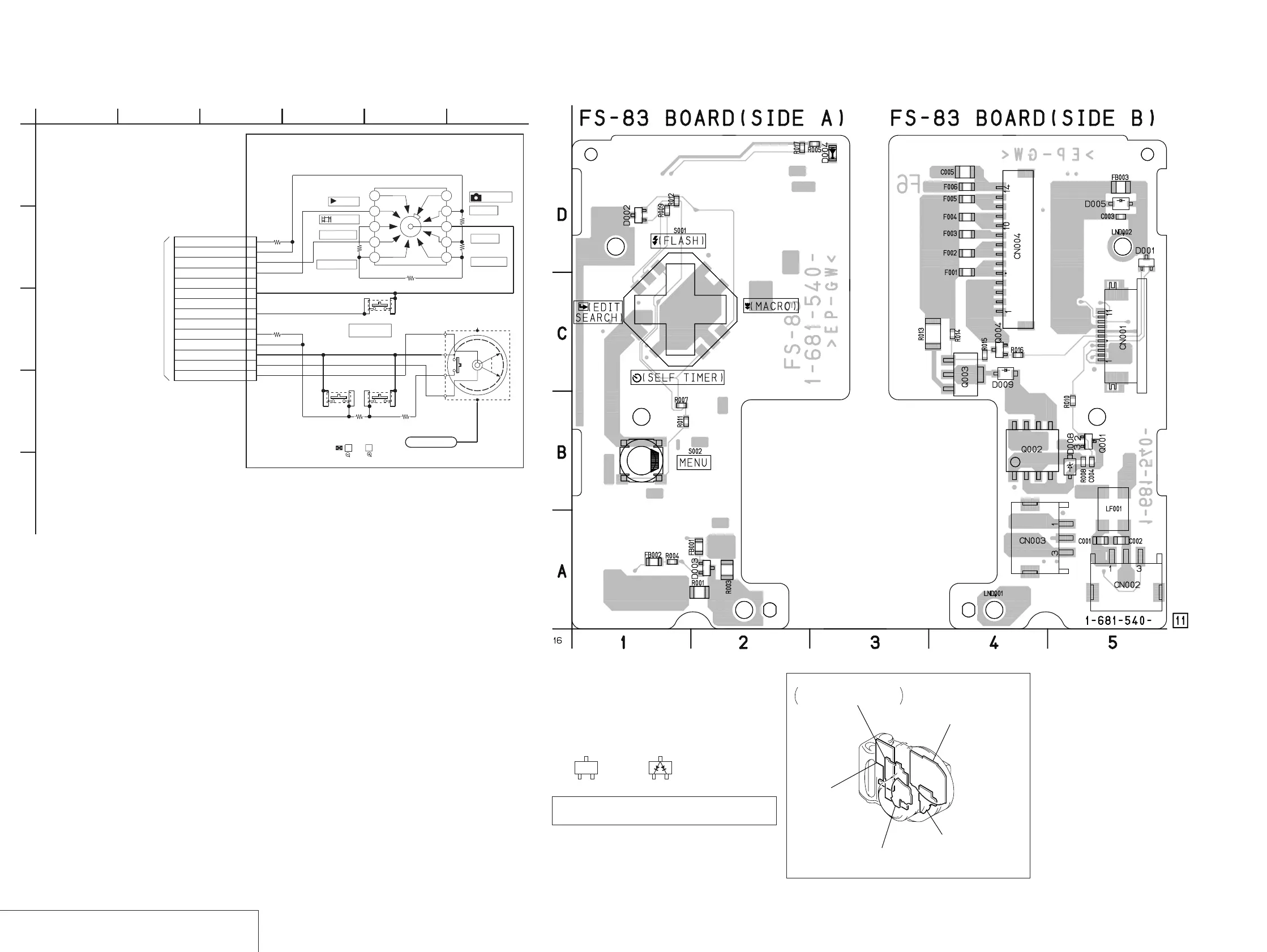
FS-83
/
FS-83 (CHARGER) PRINTED WIRING BOARD
— Ref. No. FS-83 Board; 1,000 Series —
For printed wiring board
• Refer to page 4-79 for parts location.
• FS-83 board consists of multiple layers. However, only
the sides (layers) A and B are shown.
• Chip parts
Transistor Diode
There are a few cases that the part printed on
this diagram isn’t mounted in this model.
C
BE
3
21
JK-208
(USB INTERFACE)
PK-58
(RGB DRIVE, TIMING GENERATOR, BACK LIGHT)
CD-333 (CD200)
(LENS DRIVE, CAMERA PROCESS, CCD IMAGER)
FS-83
(CHARGER)
MD-083
CD-RF PROCESS, SERVO, CD, DSP,
CD-R/RW GA, MD SYSTEM CONTROL,
EFM/ENC CONTROL
1
A
1
2
3
4
5
6
7
8
9
10
11
12
13
14
R005
4k
R003
24k
R001
20k
S003
R008
20k
S005
S004
R002
4400
R007
6600
R006
6k
R004
10k
LND001
STATICS_GND
16
(SEE PAGE
4-39)
TO
SY-67 BOARD(9/10)
CN705
6
D
4523
B
E
C
CONTROL SWITCH BLOCK(ZK-503)is replaced as a block.
So the PRINTED WIRING BOARD is omitted.
S002
(SET UP)
XPOWER_ON
B
DIAL_A
S(AE-S)
10
MODE_DIAL
CAM_3.1V
(EXEC)
UP
CAM_3.1V
6
2
M(MANUAL)
(ZOOM)
SET
S001
POWER
ON/OFF(CHG)
A
(P_AUTO)
1
DIAL_B
T
(MOVIE)
4
XPB_ON
XSET_UP
CONTROL SWITCH
BLOCK(ZK-503)
(PLAY)
SCN(SCENE)
5
W
A(AE-A)
3
KEY_AD3
N.C
GND
N.C
N.C
GND
(MODE SWITCH)

 Loading...


