5-4
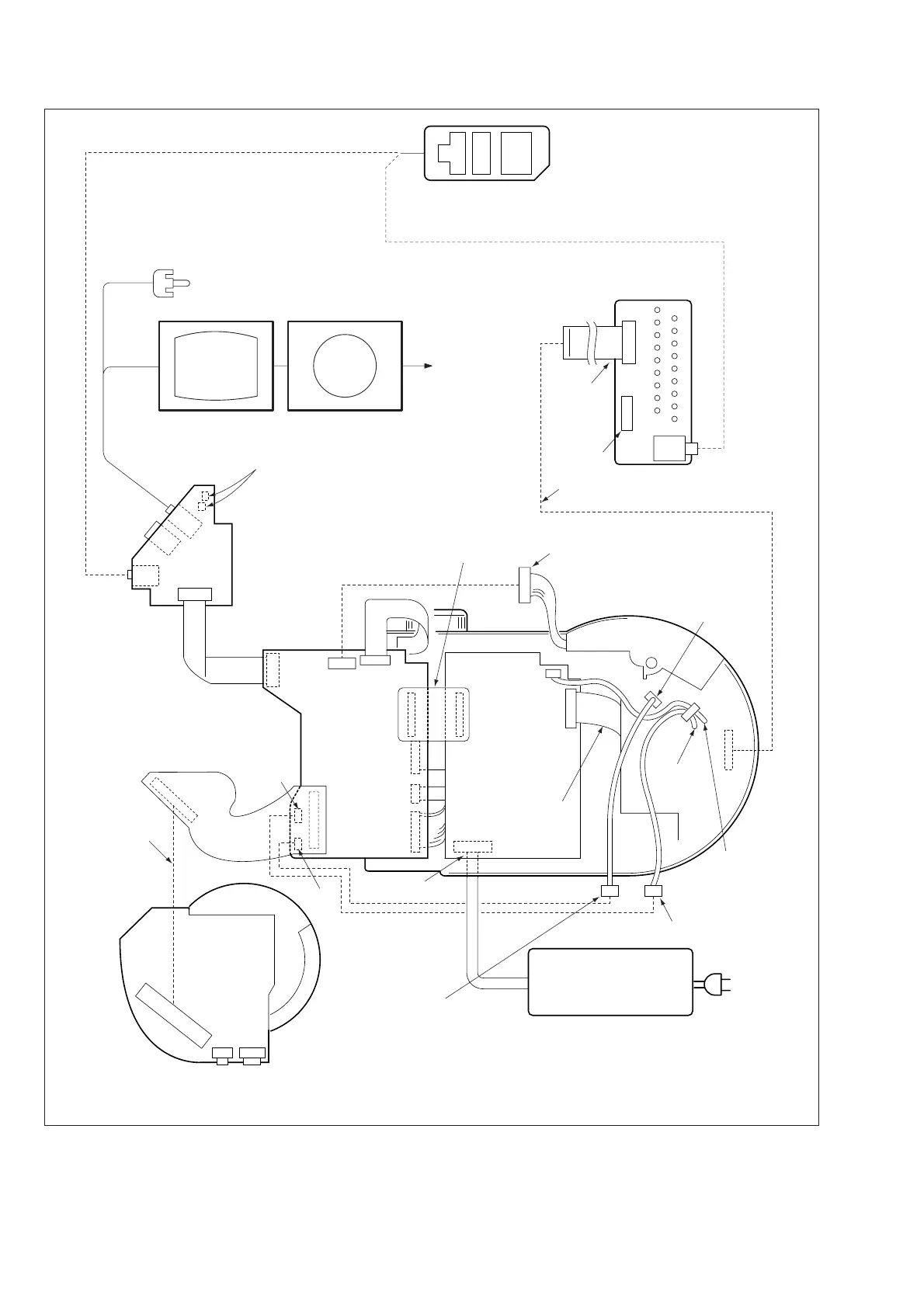
Fig. 5-1-5.
Adjustment remote
commander
Vector scope
Terminated
at 75
Ω
Color monitor
VIDEO
(Yellow)
AV OUT
jack
USB
jack
ACC (LANC)
jack
AUDIO
(Black)
CPC-9 jig
(J-6082-393-C)
18 pins
12 pins
1
18
1
18
Lid open/close detect switch (S101,S103)
Must be pressed when using the CD-R/RW
drive unit.
Must be connected when
using the flash unit.
To dew sensor
To strobe
plunger
To spindle
motor
To door lock
plunger
CN713
CN203
CN712
CN704
CN709
CN101
CN702
CN705
CN701
CN707
CN708
CN001
CN404
CN405
CN002
(Note)
PK-58
board
CN30
Must be connected when performing
the LCD system adjustments.
Must be connected when
using the flash unit.
Must be connected when
using the CD-R/RW drive unit.
Note: To open the MD-083 board, use the following extension cable between the CN002 and the
spindle motor. J-6082-374-A (18P, 0.5mm)
Must be
connected.
FP-364
SY-67
board
JK-208
board
MD-083
board
FP-361
Lens unit
DC IN jack
LANC jack
CD-333/334
board
AC IN
AC-power adaptor
(8.4Vdc)
AC-L10, AC-VQ800 etc.
Extension cable
(J-6082-487-A)
Flash unit

 Loading...


