2-1
MVC-FD81
SECTION 2
DISASSEMBLY
NOTE: Follow the disassembly procedure in the numerical order given.
NOTE: The following flow chart shows the disassembly procedure.
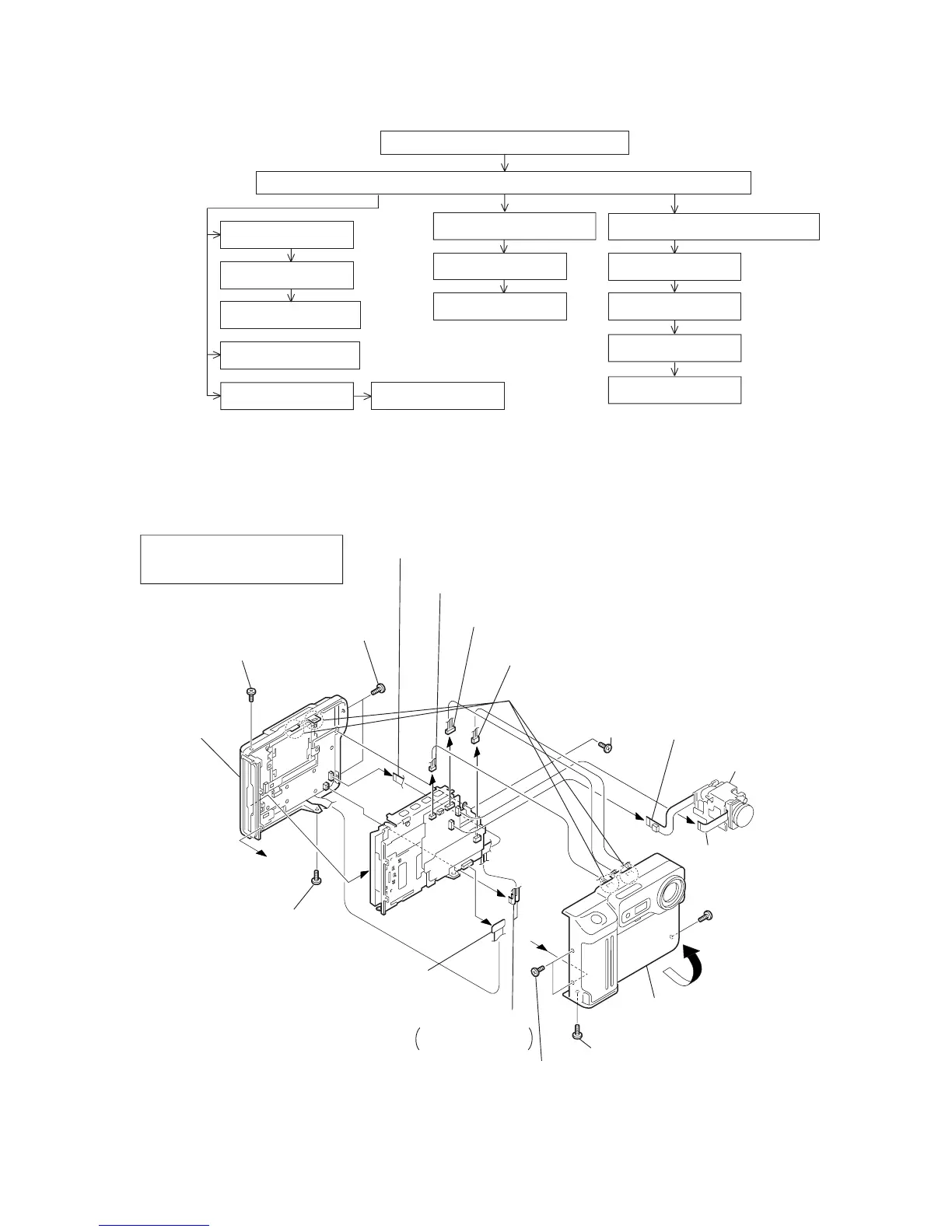
2-1. CABINET (FRONT) ASSEMBLY, CABINET (REAR) ASSEMBLY
MVC-FD81 MAVICA
2-1.
1
-
!¡
Cabinet (front) block assembly
DD-119 board
2-2.
1
-
3
Cabinet (rear) block assembly
2-1.
!∞
-
!ª
LCD, Backlight
2-3.
1
-
3
LCD
2-3.
4
,
5
FC-67 board
2-2.
4
,
5
Floppy disk drive
2-2.
6
-
!¡
MF block (50080)
2-4.
1
-
3
PK-44 board
2-3.
6
-
8
Speaker
2-3.
!º
-
!™
RL-51 board
2-4.
4
-
!º
FLASH unit
2-4.
!¡
-
!§
Lens block assembly
2-1.
!™
-
!¢
CD-206 board
2-5.
1
,
2
Lens device
2-5.
3
-
5
PK-44
Board
DD-119
FC-67
a
a
!º
Connector
(From CN301 4P, DD-119 board)
!™
Flexible board
(From CN401 20P, FC-67 board)
!£
FP-66 flexible board
(From CN101 16P, FC-67 board)
!¡
Cabinet (front) block assembly
1
-
!¡
Cabinet (front) block assembly
!™
-
!¢
Lens block assembly
!∞
-
!ª
Cabinet (rear) block assembly
!§
Connector
(From CN602 70P, FC-67 board)
9
Connector
(From CN704 13P, FC-67 board)
8
Connector
(From CN702 7P, FC-67 board)
!¶
Flexible board
(From CN601 18P, PK-44 board)
2
Two screws,
lock ace (M2
×
4)
1
Screw,
lock ace (M2
×
4)
3
Screw, lock ace (M2
×
4)
7
Claws
6
Screw, lock ace (M2
×
4)
5
Screw, lock ace (M2
×
4)
4
Two screws, lock ace (M2
×
4)
!•
Two flexible boards
From CN602 5P
×
2,
PK-44 board
!∞
Tapping screw
(B2
×
5)
!¢
Lens block assembly
!ª
Cabinet (rear)
block assembly
 Loading...