5-18
Pin No.
1
2
3
4
5
6
7
8
9
Signal Name
PANEL B-Y
PANEL Y
PANEL R-Y
REG GND
JIG XHD
JIG XVD
HSY
COM
VG
Pin No.
10
11
12
13
14
15
16
17
18
Signal Name
UNREG
LANC IN
LANC OUT
XPOWER SW
MAKER RECOG
INDEX
TRACK 00
JIG VCO
FDD RF
Table 5-1-9.
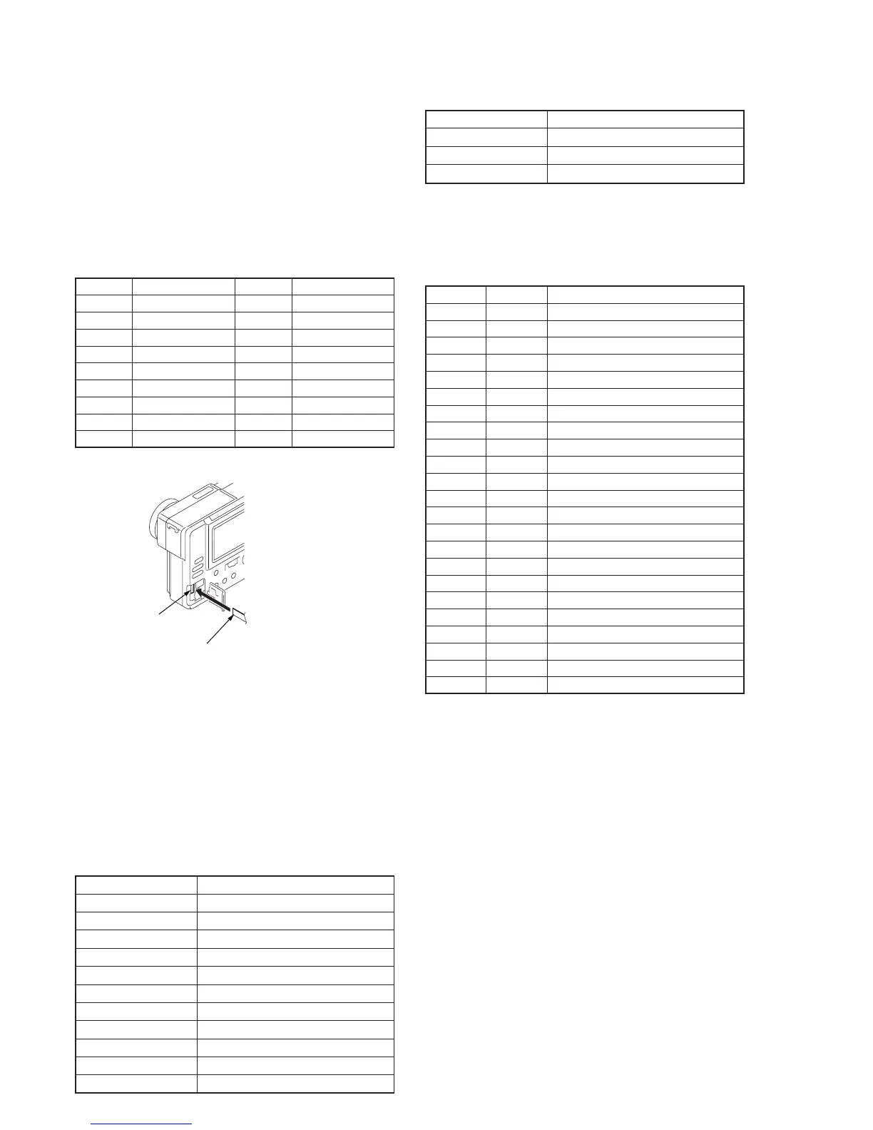
Fig. 5-1-12.
1-4. LCD SYSTEM ADJUSTMENT
Note 1: The back light (fluorescent tube) is driven by a high voltage AC
power supply. Therefore, do not touch the back light holder to
avoid electrical shock.
Note 2: When replacing the LCD unit, be careful to prevent damages
caused by static electricity.
Note 3: Set the LCD BRIGHT to the center.
[Adjusting connector]
Most of the measuring points for adjusting the LCD system are
concentrated in CN802 of the PK-44 board.
Connect the Measuring Instruments via the CPC-9 jig (J-6082-393-B).
The following table shows the Pin No. and signal name of CN802.
[Alignment disk]
Use the alignment disks (two disks as pair) shown in below.
Disk-1: TFD2-1(+) (Parts code; 8-967-990-01)
Disk-2: TFD2-2(-) (Parts code; 8-967-990-11)
Contents of alignment disk
TFD2-1(+): (Common signal) + (+17.5 µm alignment)
TFD2-2(-): (Common signal) + (–17.5 µm alignment)
Common signal
File name Signal
MVC-001C.JPG Color bars
MVC-002M.JPG Monoscope
MVC-003V.JPG V-COM adjustment signal
MVC-004W.JPG 100% white
MVC-005H.JPG 50% white
MVC-006T.JPG Stair-step signal of 10 step
MVC-007R.JPG Red single color
MVC-008G.JPG Green single color
MVC-009B.JPG Blue single color
MVC-010D.JPG Camera color bars
MVC-011N.JPG Camera monoscope
1. LCD Initial Data Input
Mode Playback
Signal Arbitrary
Adjustment Page F
Adjustment Address 30 to 38, 3B to 46, 4A, E0
Adjusting method:
1) Select page: 0, address:01, and set data: 01.
2) Select page: F, and input the data in the following table.
Note: To write in the non-volatile memory (EEPROM), press the
PAUSE button of the adjustment remote commander each time
to set the data.
Processing after Completing Adjustment
1) Select page: 3, address: 00, and set data: 29.
2) Select page: 3, address: 01, and set data: 29, and press the
PAUSE button of the adjustment remote commander.
Address
30
31
32
33
34
35
36
37
38
3B
3C
3D
3E
3F
40
41
42
43
44
45
46
4A
E0
Data
BC
80
B9
B7
BE
50
74
C8
7C
72
22
11
2E
00
11
15
00
00
44
48
33
9A
1B
Remark
Bright adjustment
Color adjustment
White balance adjustment
White balance adjustment
Contrast adjustment
VCO adjustment
V-COM adjustment
D range adjustment
V-COM level adjustment
Fixed value
Fixed value
Fixed value
Fixed value
Fixed value
Fixed value
Fixed value
Fixed value
Fixed value
Fixed value
Fixed value
Fixed value
Fixed value
Fixed value
PK-44 board
CN802
Insulator side
18 pin flexible board (Note)
Note: Don’t use the 12 pin flexible board of
CPC-9 jig. It causes damage to the unit.
 Loading...