2-3
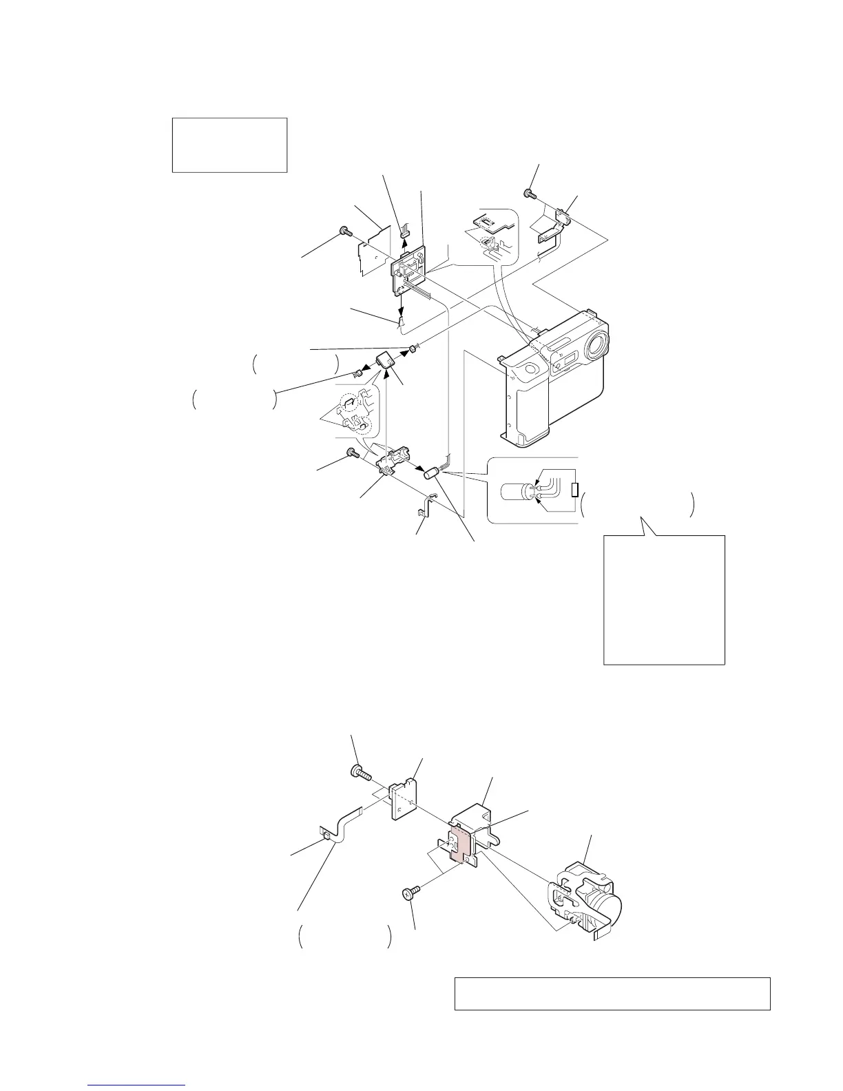
2-4. RL-51 BOARD, FLASH UNIT
2-5. CD-206 BOARD, LENS DEVICE
3
MF block (50080)
2
Three screws, tapping
(B2
×
5)
!£
Screw, tapping
(B2
×
5)
1
MF block (50080)
Flexible board
(From CN2 6P, FLASH unit)
1
-
3
MF block (50080)
4
-
!º
RL-51 board
!¡
RL holder
!™
-
!§
FLASH unit
8
Connector
From CN001 2P,
RL-51 board
7
Connector
From CN002 7P,
RL-51 board
4
Three screws, tapping
(B2
×
5)
!¡
RL holder
5
Charging capacitor
of FLASH unit
Short jig (see page 5)
1k
Ω
. 1W
parts.No.1-215-869-11
When handling the
FLASH unit, be sure
to discharge the
charging capacitor
before handling it.
For discharge short jig
to the positive (+) and
negetive (-) terminals
of the charging capacitor
for about ten seconds.
6
Ground plate (A)
!§
FLASH unit
!™
Connector
(From CN1 13P, FLASH unit)
!∞
Fuse replacement
caution label
!¢
Release
the claw
9
Release
the claws
!º
RL-51
board
6
Lens devic
 Loading...