2-2
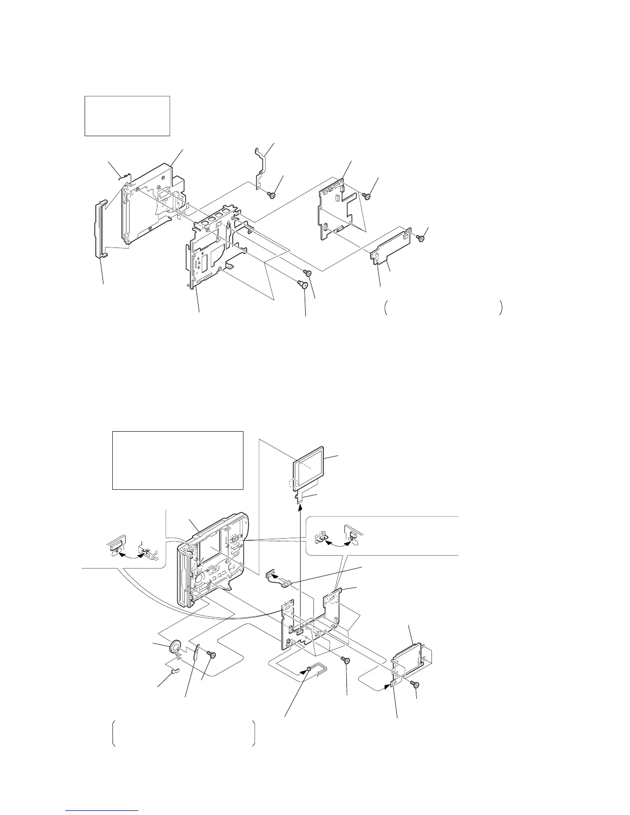
2-2. FC-67 BOARD, DD-119 BOARD, FLOPPY DISK DRIVE
2-3. PK-44 BOARD, LCD PANEL
DD-119
FC-67
Board
4
Three screws (M2
×
3)
6
Screw (M2
×
3)
7
Three screws step (M2)
8
Main frame assembly
!£
Side lid
!™
Side spring (upper)
!¡
Floppy disk drive
!º
Ground plate (H)
5
FC-67 board
9
Screw (M2
×
3)
1
Screw (M2
×
3)
3
DD-119 board
1
-
3
DD-119 board
4
-
5
FC-67 board
6
-
!¡
Floppy disk drive
!™
,
!£
Side lid
2
Connector (B to B)
From CN603 50P (FC-67 board)
to CN302 50P (DD-119 board)
PK-44
5
LCD Panel
(Release the claw
a
)
9
FP-65 flexible board
(From CN603 70P, PK-44 board)
!£
Cabinet (rear)
assembly
4
Flexible board
(From CN901 24P, PK-44 board)
8
PK-44 board
3
Cold cathode
fluorescent tube
1
-
3
Cold cathode fluorescent tube
4
,
5
LCD
6
-
8
PK-44 board
9
FP-65 flexible board
!º
-
!™
Speaker
!£
Cabinet (rear) assembly
2
Four screws, tapping
(B2
×
5)
7
Seven screws,
tapping (B2
×
5)
!º
Screw, tapping (B2
×
5)
!¡
Speaker retainer
!™
Speaker
SP insulating plate
(Note)
6
SP-151 harness
(From CN701 2P, PK-44 board)
1
Flexible board
(From CN851 20P, PK-44 board)
a
Note: When replacing the speaker,
peel off the SP insulating plate
and attach it on the new speaker.
When re-assembling
engage the switch pin
with knob groove as
shown.
When re-assembling
engage the switch pin
with knob groove as shown.
 Loading...