Table of Contents
Manual Structure
Purpose of this manual....................................................................................................................5
Related manual............................................................................................................................5
Trademarks...............................................................................................................................5
1. Service Overview
1-1. External Connectors...........................................................................................................1-1
1-1-1. Connector Input/Output Signals........................................................................................1-1
1-2. Location of Printed Wiring Boards............................................................................................1-5
1-3. Circuit Description............................................................................................................1-6
1-3-1. CMOS Block and Lens Block..........................................................................................1-6
1-3-2. Camera Block System..................................................................................................1-6
1-3-3. Video Signal System...................................................................................................1-7
1-3-4. Media Recording/Playback System....................................................................................1-7
1-3-5. Audio System...........................................................................................................1-8
1-3-6. System Control........................................................................................................1-10
1-3-7. Power Supply System.................................................................................................1-10
1-3-8. VF Block..............................................................................................................1-12
1-4. Service Tools/Measuring Equipment List...................................................................................1-13
1-4-1. Service Tools..........................................................................................................1-13
1-4-2. Measuring Equipment.................................................................................................1-13
1-5. Updating the Firmware......................................................................................................1-14
1-6. Notes on Service.............................................................................................................1-15
1-6-1. Actions to Be Taken when Replacing Parts and Boards..............................................................1-15
1-6-2. Actions to Be Taken when the Lens Has Been Replaced.............................................................1-15
1-6-3. Notes on Replacing Onboard Parts....................................................................................1-15
1-6-4. Backup Battery........................................................................................................1-15
1-7. Flexible Card Wire and Fine-Wire Coaxial Cable...........................................................................1-16
1-7-1. Disconnecting/Connecting Flexible Card Wire.......................................................................1-16
1-7-2. Disconnecting/Connecting Fine-Wire Coaxial Cable.................................................................1-16
1-8. Lead-free Solder.............................................................................................................1-18
2. Replacement of Main Parts
2-1. General Information for Parts Replacement..................................................................................2-1
2-1-1. Index....................................................................................................................2-1
2-1-2. Basic Knowledge.......................................................................................................2-6
2-1-3. Tightening Torque......................................................................................................2-7
2-2. Zoom Lens....................................................................................................................2-8
2-3. VF Block......................................................................................................................2-9
2-3-1. VF Assembly...........................................................................................................2-9
2-3-2. Loupe Assembly.......................................................................................................2-10
2-3-3. VF Loupe..............................................................................................................2-11
2-3-4. Elbow Assembly......................................................................................................2-12
2-3-5. Elbow Sub Assembly/VF Mirror Assembly..........................................................................2-13
2-3-6. SW-1603 Board/VR-351 Board.......................................................................................2-14
2-3-7. IF-1242 Board/LCD Module..........................................................................................2-16
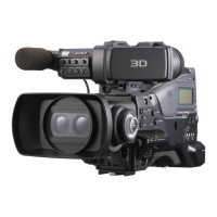
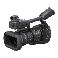
PMW-300
1