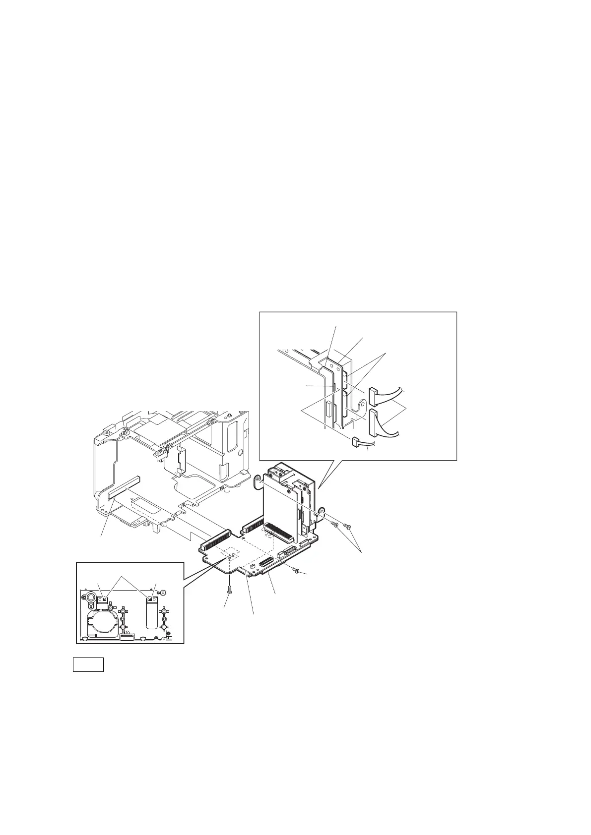
2-17. AU-357/RE-320/RE-321/RE-322 Board
Preparation
1. Remove the bottom panel assembly. (Refer to “2-5. Bottom Panel Assembly”)
2. Remove the inside panel assembly. (Refer to “2-6-1. Inside Panel Assembly”)
3. Remove the outside panel assembly. (Refer to “2-7-1. Outside Panel Assembly”)
4. Remove the rear panel assembly. (Refer to “2-8. Rear Panel Assembly”)
5. Remove the handle assembly. (Refer to “2-11-1. Handle Assembly”)
6. Remove the IO block. (Refer to “2-10. IO Block”)
7. Remove the SxS slot assembly. (Refer to “2-9-1. SxS Slot Assembly”)
8. Remove the front lens assembly. (Refer to “2-15. Front Lens Assembly”)
Procedure
1. Disconnect the harness from the connector on the RE-320 board.
2. Disconnect the two harnesses from the two connectors on the RE-321 board.
3. Remove the five screws (P2 x 4).
4. Remove the AU-357 board from the connector on the DPR-355 board.
Positioning pins
U groove U groove
P2 x 4
P2 x 4
(a)
(c)
(b)
P2 x 4
Connector
Connectors
AU-357 board
Bracket AU
Connector
(DPR-355 board)
RE-321 board
Harnesses
Harness
RE-320 board
Note
When installing these precision screws, push the U groove of the bracket AU against the positioning pin, and tighten
screws (a) to (c) in alphabetical order.
5. Remove the screw (P2 x 4).
PMW-300
2-49