3
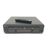
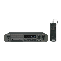
RCD-W3
TABLE OF CONTENTS
1. SERVICING NOTE .......................................................... 4
2. GENERAL .......................................................................... 8
3. DISASSEMBLY
3-1. Top Case............................................................................... 9
3-2. Tray Door, Front Panel Assy .............................................. 10
3-3. HP board, FL board, VOL board ........................................ 10
3-4. Back Panel ......................................................................... 11
3-5. Audio Board ....................................................................... 11
3-6. Power Board ...................................................................... 12
3-7. CDP Deck assy (Deck A), CD-R Deck Assy (Deck B) ..... 12
3-8. BD-P Board (Deck A) ........................................................ 13
3-9. CDP Mechanism Assy (Deck A) ........................................ 13
3-10.Spindle Motor Assy, Optical Pick-Up Block (Deck A)...... 14
3-11.BD-R Board........................................................................ 14
3-12.CD-R Mechanism Assy (Deck B) ...................................... 15
4. ELECTRICAL ADJUSTMENT ................................... 16
5. DIAGRAMS
5-1. Circuit Boards Location .................................................... 21
5-2. Block diagrams – CD-R Section (1/2) – ........................... 23
Block diagrams – CD-R Section (2/2) – ........................... 24
Block diagrams – CDP Section –...................................... 25
Block diagrams – Audio Section – ................................... 26
Block diagrams – Power Section – ................................... 27
5-3. Printed Wiring Board – BD-R Section (Side A) – ............ 28
Printed Wiring Board – BD-R Section (Side B) – ............ 29
5-4. Schematic Diagram – BD-R Section (1/6) –..................... 30
5-5. Schematic Diagram – BD-R Section (2/6) –..................... 31
5-6. Schematic Diagram – BD-R Section (3/6) – ..................... 32
5-7. Schematic Diagram – BD-R Section (4/6) –..................... 33
5-8. Schematic Diagram – BD-R Section (5/6) –..................... 34
5-9. Schematic Diagram – BD-R Section (6/6) – ..................... 35
5-10. Printed Wiring Board – Audio Section –........................... 36
5-11. Schematic Diagram – Audio Section – ............................ 37
5-12. Printed Wiring Board – Panel Section – ........................... 38
5-13. Schematic Diagram – Panel Section – ............................. 39
5-14. Printed Wiring Board – Power Section – ......................... 40
5-15. Schematic Diagram – Power Section – ............................ 41
5-16. Printed Wiring Board – BD-P Section –........................... 42
5-17. Schematic Diagram – BD-P Section – ............................. 42
5-18. IC Pin Functions Description ........................................... 43
5-19. IC Block Diagrams ........................................................... 48
6. EXPLODED VIEWS
6-1. Front Panel Section ............................................................. 52
6-2. Chassis Section ................................................................... 53
6-3. CD Play Section (Deck A) .................................................. 54
6-4. CD Record Section (Deck B).............................................. 55
7. ELECTRICAL PARTS LIST .................................56
Error Messages
The following table explains the error messages that appear in the
display.
Message Explanation
CHECK DISC • A record-related button has been
pressed when a finalized disc is in
the DECK B.
• A record-related button has been
pressed when a standard CD is in
the DECK B.
DATA DISC A non-audio CD-ROM or a CDVideo
disc has been placed in the machine.
DISC ERROR • An unfinalized disc has been placed in
the DECK A.
• There is a problem with the disc.
• A DVD disc has been placed in the unit.
DISC FULL There is not enough time left on the disc
to complete a planned recording.
ERROR There is a problem with the tray.
FAILED A dubbing has not been completed
properly.
FULL More than 20 tracks have been
programmed.
NO AUDIO A record-related button has been
pressed when a non-audio disc is in
the DECK B.

 Loading...