19
Preparatory Settings
To output as HD-SDI
To output as SD-SDI
To output as VBS
Constantly outputting a return video
• When a CCU is connected, one of the signals being
supplied to the CCU can be output from the camera.
• The last selected return signal is output.
• The same character information as that displayed on the
viewfinder screen can be added to the output signal by
setting CHARACTER to ON on the <SDI OUT> or <TEST
OUT> page.
To output as HD-SDI
To output as SD-SDI
To output as VBS
Outputting the same image as that on the
viewfinder screen
• With HD-SDI, you can obtain a signal that includes the same
information as that being displayed on the viewfinder
according to the settings for VF MARKER, CHARACTER,
VF DETAIL, ZEBRA, etc. The ON/OFF or other settings for
adding information are common to those for the viewfinder.
The output is synchronized with switching among Y, R, G,
and B or switching to a return signal.
• With SD-SDI or VBS, the output is synchronized only with
switching between a return signal and the camera image. It
does not correspond to switching among Y, R, G, and B.
Information other than CHARACTER (such as VF
MARKER, VF DETAIL, and ZEBRA) cannot be added to the
output.
With the settings for outputting the same image as that on the
viewfinder, the output will be obtained in 1080i, even if the
format setting is 720P.
To output as HD-SDI
To output as SD-SDI
To output as VBS
Outputting a prompter signal (when an HXCU-
100 is connected)
The VBS signal supplied to the PROMPTER connector of the
CCU is output from the PROMPTER/GENLOCK/RET IN
connector of the camera.
Outputting a prompter signal (when an HSCU-
300 is connected)
The VBS signal supplied to the PROMPTER 1 connector of
the CCU is output from the PROMPTER/GENLOCK/RET IN
connector of the camera.
The VBS signal supplied to the PROMPTER 2 connector or
the SDI prompter signal supplied to the RETURN INPUT
connector of the CCU is not output from the camera.
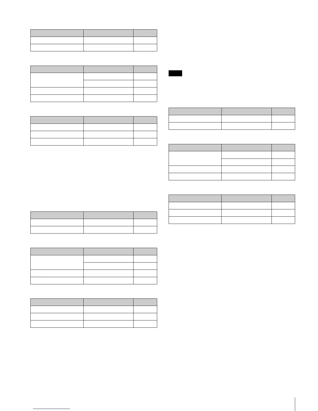
Menu page Item Setting
<POWER SAVE> SDI OUT ACTIVE
<SDI OUT> OUTPUT MAIN
Menu page Item Setting
<POWER SAVE> SDI OUT ACTIVE
DOWN CONVERTER ACTIVE
<DOWN CONVERTER> OUTPUT SIGNAL MAIN
<SDI OUT> OUTPUT SD-SDI
Menu page Item Setting
<POWER SAVE> DOWN CONVERTER ACTIVE
<DOWN CONVERTER> OUTPUT SIGNAL MAIN
<TEST OUT> OUTPUT VBS
Menu page Item Setting
<POWER SAVE> SDI OUT ACTIVE
<SDI OUT> OUTPUT RET
Menu page Item Setting
<POWER SAVE> SDI OUT ACTIVE
DOWN CONVERTER ACTIVE
<DOWN CONVERTER> OUTPUT SIGNAL RET
<SDI OUT> OUTPUT SD-SDI
Menu page Item Setting
<POWER SAVE> DOWN CONVERTER ACTIVE
<DOWN CONVERTER> OUTPUT SIGNAL RET
<TEST OUT> OUTPUT VBS
Note
Menu page Item Setting
<POWER SAVE> SDI OUT ACTIVE
<SDI OUT> OUTPUT VF
Menu page Item Setting
<POWER SAVE> SDI OUT ACTIVE
DOWN CONVERTER ACTIVE
<DOWN CONVERTER> OUTPUT SIGNAL VF
<SDI OUT> OUTPUT SD-SDI
Menu page Item Setting
<POWER SAVE> DOWN CONVERTER ACTIVE
<DOWN CONVERTER> OUTPUT SIGNAL VF
<TEST OUT> OUTPUT VBS