10
Installation
• When the camera is used in standalone status without
connecting a CCU, use this connector for input of an
external sync signal (BB or 3-level sync). If a VBS signal is
input, you can check the input image by pressing the RET
button.
• Even when a BB signal is used for the external sync signal,
no subcarrier phase-lock function is available for the VBS
output signal.
• As PROMPTER is set to PWR SAVE at the factory, a
prompter signal is not output. Set it to ACTIVE on the
POWER SAVE page of the MAINTENANCE menu.
f REMOTE connector (8-pin)
For connection to an RM-B150/B750 Remote Control Unit or
RCP-1000-series Remote Control Panel.
When a CCU is used in combination, this connector functions
as the trunk signal input/output. Do not connect any remote
control device to this connector.
g TEST OUT connector (BNC type)
To output an analog signal.
This supplies a VBS signal, an HD-Y signal equal to the signal
output from the VF connector, an HD-SYNC signal, or an SD-
SYNC signal, depending on which of these you have selected
on the menu.
The VBS output signal has no subcarrier phase-lock function
with respect to external sync signals.
h AUDIO IN CH1 connector (XLR 3-pin) and input select
switch
Connect a channel 1 audio signal and set the switch according
to the connected source device.
LINE: When a line-level (0 dBu) signal source is connected
MIC: When an external microphone is connected
+48V: To supply power of +48 V to the connected external
microphone
i MIC 1 (microphone 1) select switch
Select the microphone for channel 1.
FRONT: To use the microphone connected to the MIC 1 IN
connector
REAR: To use the microphone connected to the AUDIO IN
CH1 connector
j AUDIO IN CH2 connector (XLR 3-pin) and input select
switch
Connect a channel-2 audio signal and set the switch according
to the connected source device in the same manner as with
channel 1.
k SDI (serial digital interface) connector (BNC type)
For HD-SDI or SD-SDI signal output.
You can select from among camera line signal, return signal,
and VF signal for the output with a menu operation.
Installation
Connecting a Camera Control Unit
(CCU)
When operating the camera in a system with a CCU, connect
between the CCU connector of the camera and the CAMERA
connector of the CCU, using a triax cable.
When required, secure the cable, using the supplied cable
clamp belt.
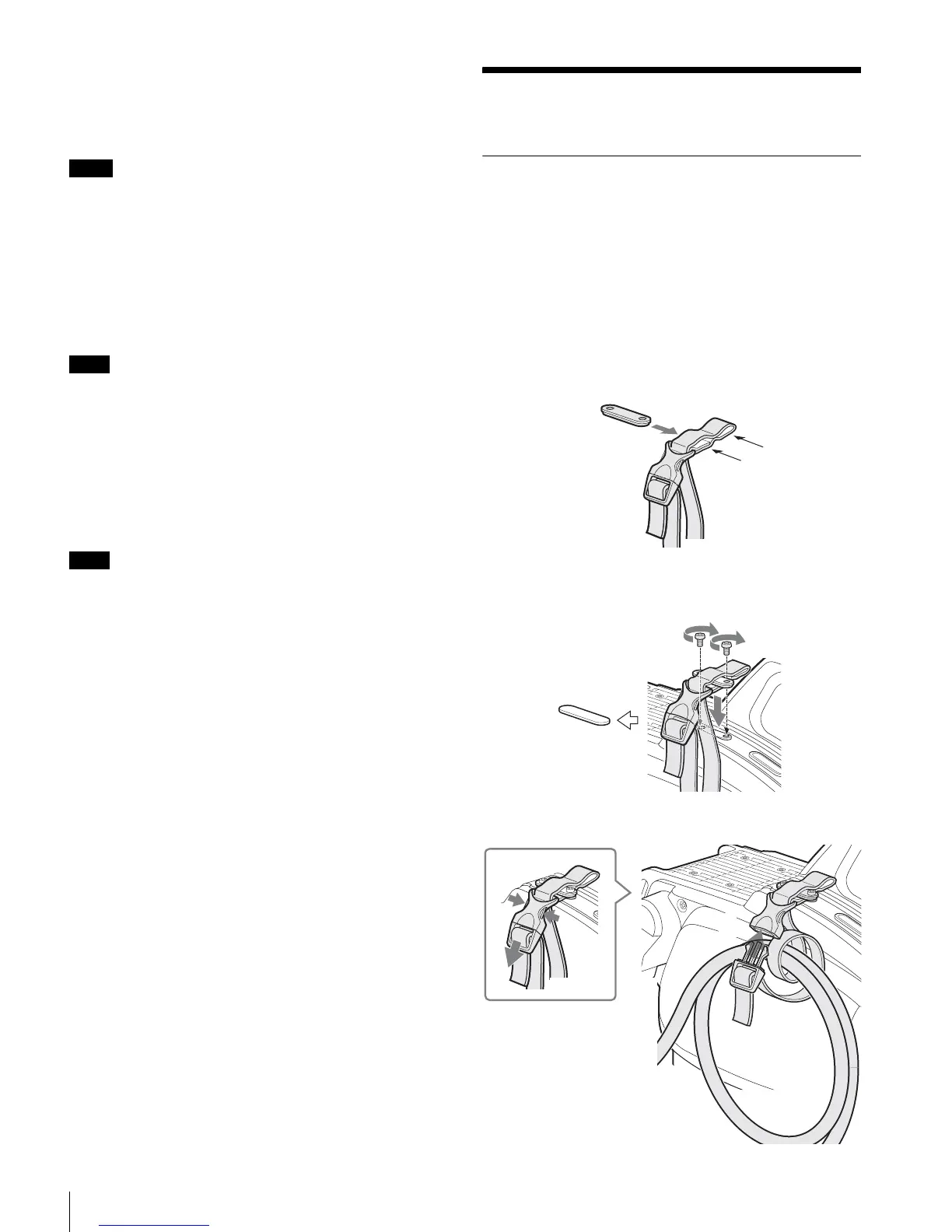
To use the cable clamp belt
1 Insert the belt bracket C into hole A or B of the cable
clamp belt.
2 1 Remove the back screw-hole cover on the top of
the camera and 2 secure the cable clamp belt to the
camera, using the two supplied screws (+B3×10).
3 1 Release the buckle, 2 bundle the cable with the
belt, 3 then lock the buckle again.
Notes
Note
Note
A
B
C
1
2
1
2
3