— 5 —
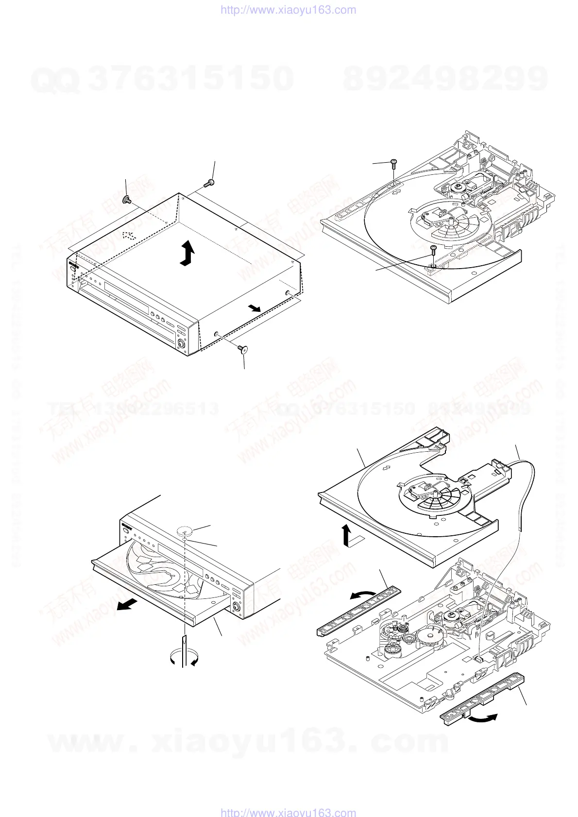
1. NOTE ON REMOVING THE UPPER
CASE
1) Remove the four tapping screws and three screws. (See Fig. 1)
2) Open the sides of case. (See Fig. 1)
3) Remove the upper case in the direction of the arrow A.
2. DISC REMOVAL PROCEDURE
1) Insert a flat-head (-) screwdriver into a hole at the bottom, and
rotate the cam gear in the direction of the arrow A. (See Fig.2)
Two tapping screws
Two tapping screws
Three screws (B3)
A
3. NOTE ON REMOVING THE TABLE
ASS’Y
1) Remove the two screws. (See Fig. 3)
A
Cam gear
Ta ble
Hole
Screw
(M2.6
×
8)
Screw
(M2.6
×
8)
2) Remove the two Plates (guide) in the direction of the arrows
A and B.
3) Remove the Table ass’y in the direction of the arrow C.
4) Remove the Flexible flat cable (See Fig. 4).
A
B
C
Plate (guide)
Plate (guide)
Table ass'y
Flexible flat cable
(FMS-18: CN002)
Fig. 1.
Fig. 2.
Fig. 3.
Fig. 4.
SERVICE NOTE
w
w
w
.
x
i
a
o
y
u
1
6
3
.
c
o
m
Q
Q
3
7
6
3
1
5
1
5
0
9
9
2
8
9
4
2
9
8
T
E
L
1
3
9
4
2
2
9
6
5
1
3
9
9
2
8
9
4
2
9
8
0
5
1
5
1
3
6
7
3
Q
Q
TEL 13942296513 QQ 376315150 892498299
TEL 13942296513 QQ 376315150 892498299
http://www.xiaoyu163.com
http://www.xiaoyu163.com
 Loading...