HT-MT300/MT301
17
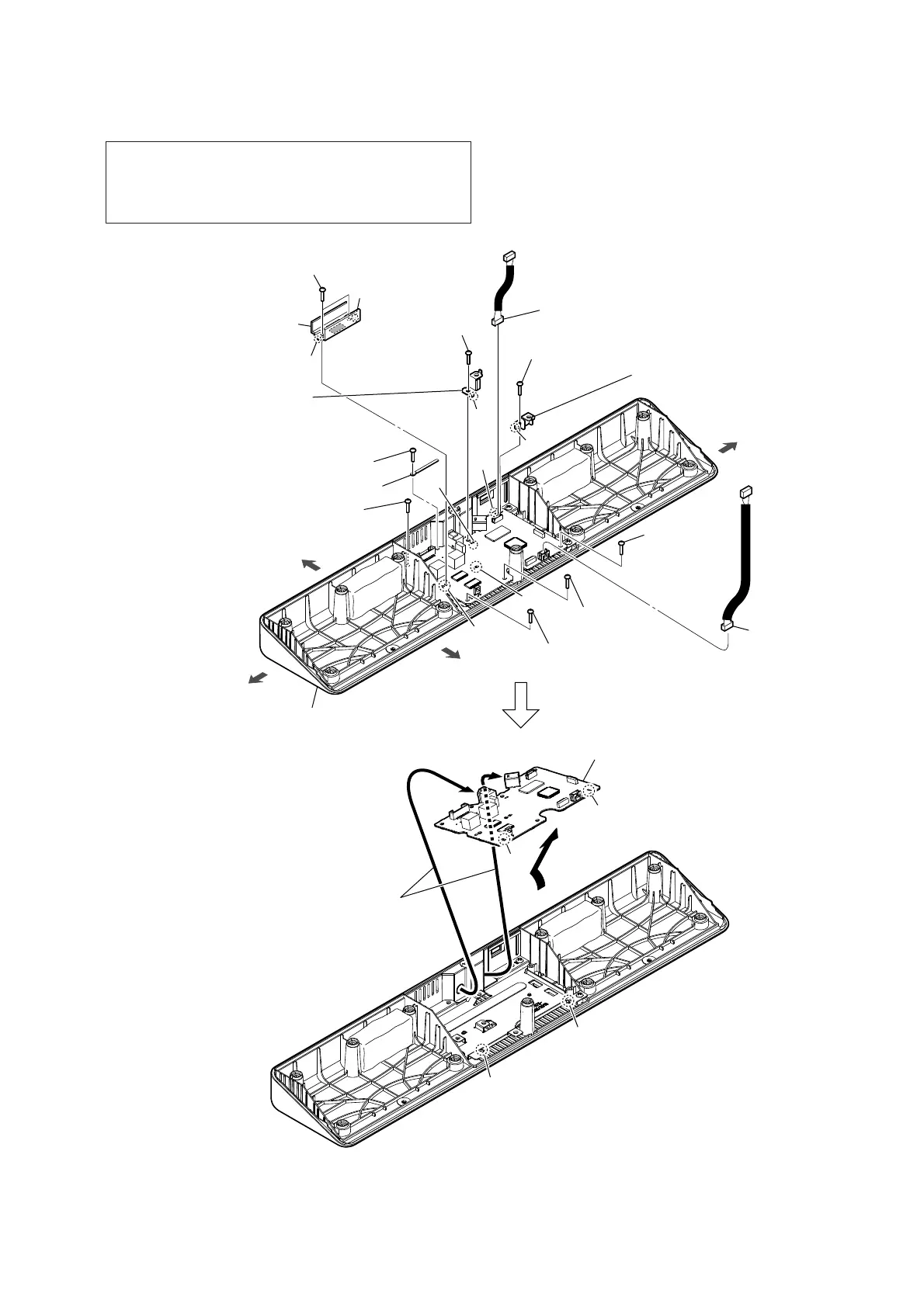
2-11. MAIN BOARD
0 Draw the jack and connector
out of the two holes in bottom
cabinet block.
bottom cabinet block
5 two screws
(BVTP3 u 8)
7 screw
(BVTP3 u 8)
7 screw
(BVTP3 u 8)
7 screw
(BVTP3 u 8)
3 screw
(BVTP3 u 8)
3 screw
(BVTP3 u 8)
7 screw
(BVTP3 u 8)
7 screw
(BVTP3 u 8)
8 wiring stopper
front side
rear side
left side
right side
boss
rib
rib
boss
rib
rib
hole
hole
qa MAIN board
Note 4:
When installing the MAIN board,
align the two ribs and two holes.
6 heat sink
Note 3:
When installing the heat
sink, align the two bosses
and two holes.
4 analog bracket
Note 2:
When installing the analog
bracket, align the rib and hole.
4 analog bracket
Note 2:
When installing the analog bracket,
align the rib and hole.
1 JACK board cable
connector (CN3000)
2 JACK board cable
connector (CN3401)
9
hole
hole
hole
hole
Note 1: When the MAIN board is replaced, refer to “NFC CONNEC-
TION CHECKING METHOD” on page 4, “WIRELESS
CONNECTION (LINK) WORK OF BAR SPEAKER AND
SUBWOOFER” on page 5 and “SPREADING OF COM-
POUND” on page 7.