7-2
2-3. SERVO SYSTEM ADJUSTMENT
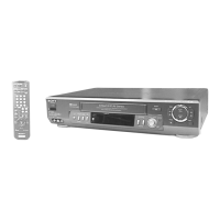
2-3-1. RF Switching Position Adjustment
(MA-377 Board)
Purpose:
Adjust the interval between A ch and B ch of tape playback out-
put.
Improve the interchangeability with other tapes and sets.
When it is out of order, the interval appears on the screen, the
screen is disturbed.
Mode PB
Signal Alignment tape SP mode color
bar
Measurement Point CH1: VIDEO LINE OUT
CH2: Pin 3 of CN202
(RF SWP)
Measuring Instrument Oscilloscope
Specified Value 6.5 ± 0.5 H (416 ± 32 µsec) PAL
6.5 ± 0.5 H (410 ± 32 µsec)
NTSC
Adjusting Method:
1) Connect MA-377 board JS401 to the GND for about 1 secont
to activate the RF switching position adjustment mode.
2) Check appear “A P” on FL display.
3) Using the channel + and – buttons, adjust to 6.5 ± 0.5 H.
4) Press the pause button.
Fig. 7-2-3.
Approx. 1 Vp-p
Approx. 5 Vp-p
V
enargement
CH2
CH1
CH2
CH1
Vertical sync. signal
6.5 ± 0.5 H
(416 ± 32 µsec) PAL
(410 ± 32 µsec) NTSC
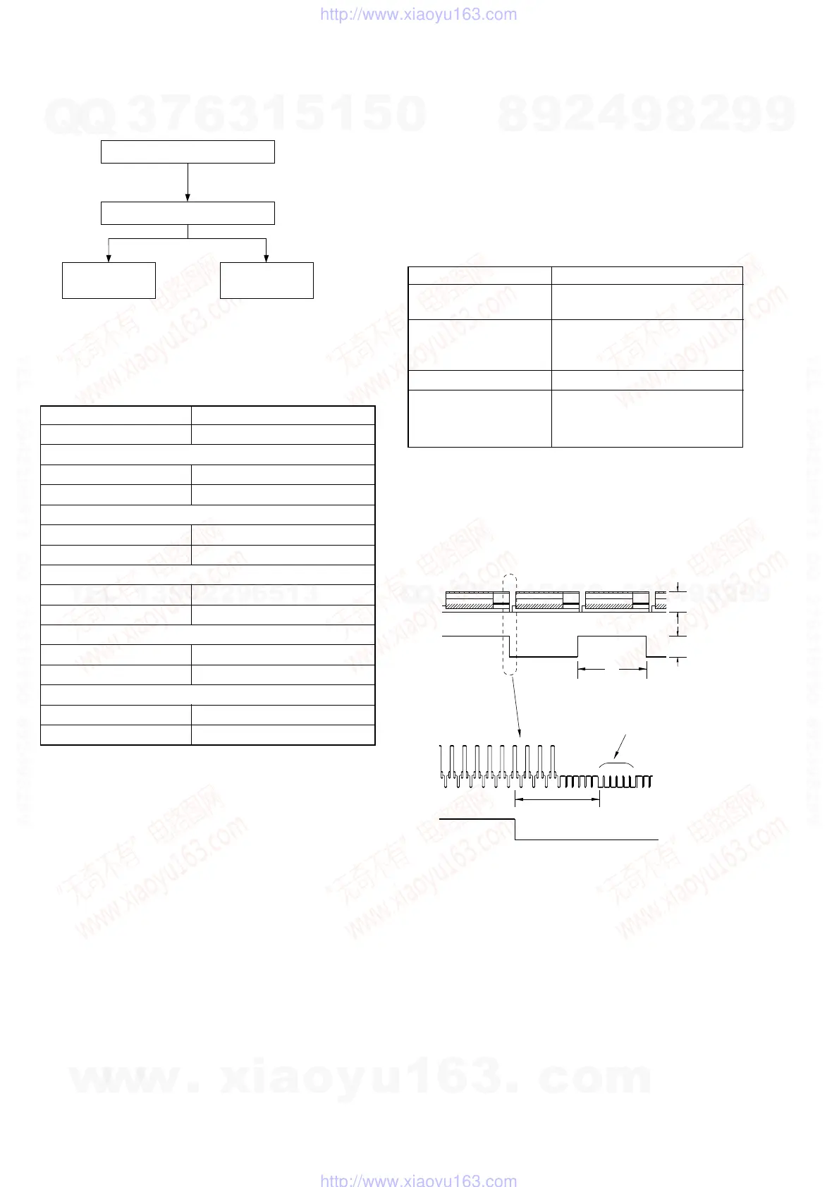
2-1-6. Adjusting Sequence
Make the electrical adjustment in the following sequence.
Mode E-E
Measuring Instrument Digital voltmeter
+F, –F check
Measurement Point Pin qf (+F), Pin qh (–F) of CN102
Specified Value 2.5 ± 0.4 V
–13 V check
Measurement Point Pin qk of CN102
Specified Value –11.75 ± 1.25 V
+6 V check
Measurement Point Pin 3, 4 of CN102
Specified Value 5.9 ± 0.2 V
+13 V check
Measurement Point Pin 5, 6 of CN102
Specified Value 13.8 ± 1.2 V
+38 V check
Measurement Point Pin 1, 2 of CN102
Specified Value Max 40 V
2-2. POWER SUPPLY ADJUSTMENT
2-2-1. Power Supply Check
(PSM17-501 BOARD)
Checking Method:
1) Confirm that each voltage meets its specified value.
Power supply adjustment
Servo system adjustment
Audio system
adjustment
Tuner system
adjustment
w
w
w
.
x
i
a
o
y
u
1
6
3
.
c
o
m
Q
Q
3
7
6
3
1
5
1
5
0
9
9
2
8
9
4
2
9
8
T
E
L
1
3
9
4
2
2
9
6
5
1
3
9
9
2
8
9
4
2
9
8
0
5
1
5
1
3
6
7
3
Q
Q
TEL 13942296513 QQ 376315150 892498299
TEL 13942296513 QQ 376315150 892498299
http://www.xiaoyu163.com
http://www.xiaoyu163.com