7-5 7-6 E
4. Overall Level Characteristic and Distortion Factor
Check
Purpose:
Check the record level, play level, and distortion factor against the
reference input.
Mode REC and PB (SP mode)
Signal 400 Hz, –7.5 dBs
Measurement point Audio output terminal
Measurement equipment Audio level meter and distortion
factor meter
Specified value Playback level: –7.5 ± 4.0 dBs
Distortion factor: 4% or less
Confirmation Method:
1) Supply an audio signal of 400 Hz, –7.5 dBs simultaneously to
both L and R channels of Audio Line Input.
2) Make recording
3) Play back a recorded portion.
4) Confirm that a playback level is –7.5 ± 4.0 dBs. (mono audio)
5) Confirm that a distortion factor is within 4%.
5. Overall S/N Check
Purpose:
Confirm that the S/N is within the specification.
Mode REC and PB (SP mode)
Signal Short
Measurement point Audio output terminal
Measurement equipment Audio noise meter
Specified value –46.0 dBs or less
Confirmation Method:
1) Connect both L and R channels of audio line input to the GND.
2) Start recording.
3) Play the recorded part to confirm that the noise is below –46.0
dBs.
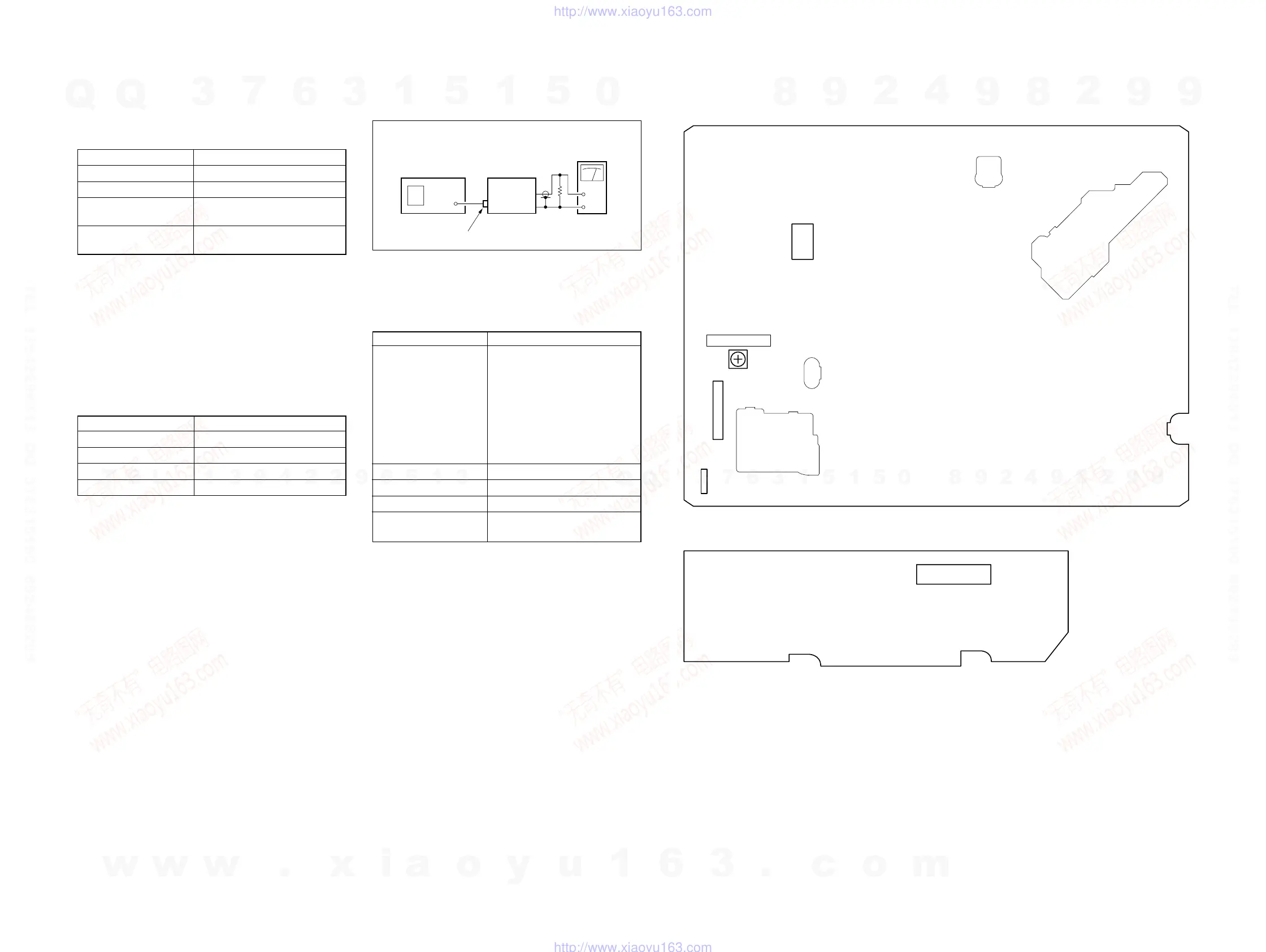
2-5. TUNER SYSTEM ADJUSTMENT
[Connection]
Fig. 7-2-6
2-5-1. Separation Adjustment (SLV-EX8S/EX9S)
Purpose:
Mixed audio signal separate Lch and Rch.
Mode E-E
Signal VIDEO:
color bar
(87.5% modulation)
AUDIO:
L 1 kHz 100% modulation
R no signal
ELECTRIC FIELD:
60–80 dBs/75 W Tem
Measurement point Pin qs of IC701
Measurement equipment Audio level meter
Adjusting Element RV701
Specified value –9.9 ± 0.2 dBm
(700 ± 14 mVp-p)
47 k
VCR
Audio level
meter
Up channel
convertor
RF IN
2-6. PARTS ARRANGEMENT DIAGRAM FOR ADJUSTMENTS
MA-377 BOARD (Component Side)
PSM17-501 BOARD (Conductor Side)
1
2
19
18
CN102
CN202
RV701
IC701
JS401
13
1
1
4
SEPARATION
w
w
w
.
x
i
a
o
y
u
1
6
3
.
c
o
m
Q
Q
3
7
6
3
1
5
1
5
0
9
9
2
8
9
4
2
9
8
T
E
L
1
3
9
4
2
2
9
6
5
1
3
9
9
2
8
9
4
2
9
8
0
5
1
5
1
3
6
7
3
Q
Q
TEL 13942296513 QQ 376315150 892498299
TEL 13942296513 QQ 376315150 892498299
http://www.xiaoyu163.com
http://www.xiaoyu163.com