100
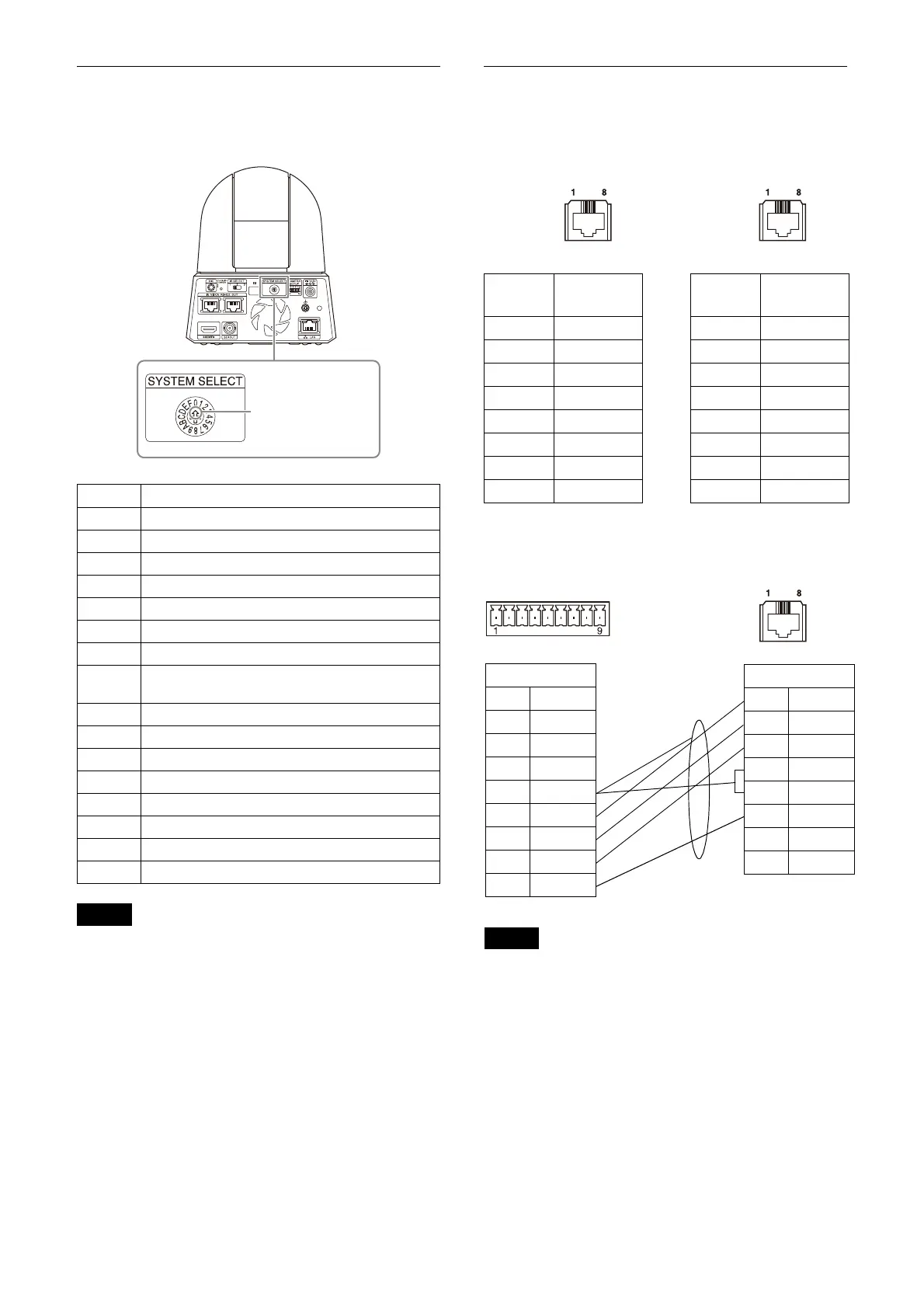
SYSTEM SELECT switch settings
The video output format for the HDMI/SDI OUT
terminal can be set with this switch.
Notes
• Be sure to set the switch before you turn on the
camera.
Turn on the power after you set the switch.
• Be sure to use a Phillips-head screwdriver
wh
en changing the switch position. If you use
a tool other than the designated screwdriver,
the crossed groove may be damaged.
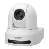
Pin array of the VISCA RS-422
terminal and how to use it
Pin array of VISCA RS-422 terminal
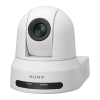
Connection diagram with remote
controller RM-IP10
Notes
• Connect the GNDs of both devices together to
stabilize the voltage level of the signal.
• When preparing cables, use network cables of
categ
ory 5e or more.
No. Video output format/Frame rate
0 3840x2160/29.97p
1 1920x1080/59.94p
2 1920x1080/59.94i
3 1920x1080/29.97p
4 1280x720/59.94p
5 RESERVE
6 REMOTE
7 HDMI : 640x480/59.94p
SDI OUT : 1280x720/59.94p
8 3840x2160/25p
9 1920x1080/50p
A 1920x1080/50i
B 1920x1080/25p
C 1280x720/50p
D RESERVE
E 3840x2160/23.98p
F 1920x1080/23.98p
Select your desired
video output format.
Pin
No.
Function Pin
No.
Function
1 TX– 1 RX–
2 TX+ 2 RX+
3 RX– 3 TX–
4 GND 4 GND
5 GND 5 GND
6 RX+ 6 TX+
7 N.C. 7 N.C.
8 N.C. 8 N.C.
RM-IP10
1N.C.
2N.C.
3N.C.
4N.C.
5GND
6RX–
7RX+
8TX–
9TX+
Camera
1TX–
2TX+
3RX–
4GND
5GND
6RX+
7N.C.
8N.C.
Shield