STR-DN1050
24
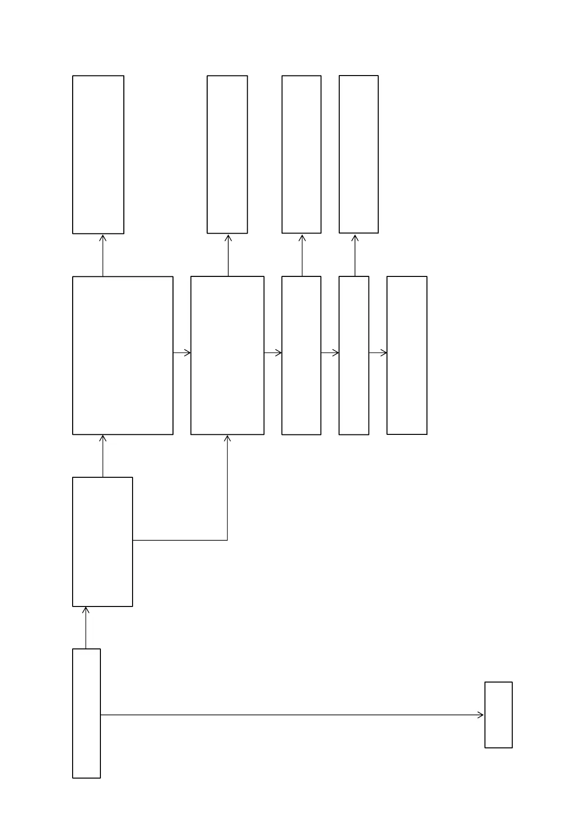
Flow of Repair (when sound is not outputted) (4/5)
Check that the sound from the HDMI
input is outputted.
Perform the “SOFTWARE VERSION
DISPLAY MODE” (refer to page 17
on the original service manual), and
check that the video micro-processor
version is not “0.00”.
Check that voltages of the connector pins
on the DIGITAL board are the following value.
DIGITAL board:
CN1501 pin 3 : +4V
CN1501 pin 5, 6 : +6V
CN1501 pin 7 : +4.5V
CN1501 pin 8 : +4.24V
CN1501 pin 9, 10 : +2.4V
CN1501 pin 11, 12 : +2.5V
Check the following parts and the surrounding
circuit, and exchange the defective parts.
DCDC board: IC1905, IC1906, IC1907,
IC1908, IC1909, IC1910, F940, F941
Check the following parts and the surrounding
circuit, and exchange the defective parts.
DIGITAL board: IC3506
Check the following parts and the surrounding
circuit, and exchange the defective parts.
DIGITAL board: IC2100, IC3001
Check the following parts and the surrounding
circuit, and exchange the defective parts.
DIGITAL board: X3000
Check that voltage of the following pin is 3.3 V,
1.3 V.
DIGITAL board: IC3506
pin18 : 1.2V ~ 1.3V
pin112: 3.3V(VOUT)
pin173: 3.3V
Check that voltage of the following pin is 3.3 V.
DIGITAL board: IC3000
pin57: 3.3V(RESET)
Check that the X3000 on the DIGITAL board is
oscillated normally.
Check the following parts and the surrounding
circuit, and exchange the defective parts.
DIGITAL board: IC3000
– Continued
on page 25 –
OK
OK
NG
NG
NG
NG
NG
NG
OK
OK
OK
OK