SERVICE MANUAL
Sony Corporation
Published by Sony EMCS (Malaysia) PG Tec
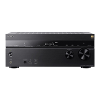
STR-DN860/DN1060
MULTI CHANNEL AV RECEIVER
9-890-661-01
2015B80-1
©
2015.02
Ver. 1.0 2015.02
US Model
Canadian Model
AEP Model
UK Model
Australian Model
Taiwan Model
STR-DN860
– Continued on next page –
Photo: STR-DN1060
This receiver incorporates Dolby* Digital and Pro
Logic Surround and the DTS** Digital Surround
System.
* Manufactured under license from Dolby Labo-
ratories. Dolby, Pro Logic, Surround EX, and
the double-D symbol are trademarks of Dolby
Laboratories.
** For DTS patents, see http://patents.dts.com.
Manufactured under license from DTS
Licensing Limited. DTS, DTS-HD, the
Symbol, & DTS and the Symbol together are
registered trademarks, and DTS-HD Master
Audio is a trademark of DTS, Inc. © DTS, Inc.
All Rights Reserved.
This receiver incorporates High-Definition
Multimedia Interface (HDMI™) technology.
The terms HDMI and HDMI High-Definition
Multimedia Interface, and the HDMI Logo are
trademarks or registered trademarks of HDMI
Licensing LLC in the United States and other
countries.
Apple, the Apple logo, AirPlay, iPad, iPhone,
iPod, iPod classic, iPod nano, iPod touch,
and Retina are trademarks of Apple Inc.,
registered in the U.S. and other countries.
iPad Air and iPad mini are trademarks of Apple Inc.
App Store is a service mark of Apple Inc.
All other trademarks and registered trademarks
are of their respective holders. In this manual, ™
and
®
marks are not specified.
“Made for iPod,” “Made for iPhone,” and “Made
for iPad” mean that an electronic accessory has been
designed to connect specifically to iPod, iPhone,
or iPad, respectively, and has been certified by the
developer to meet Apple performance standards.
Apple is not responsible for the operation of
this device or its compliance with safety and
regulatory standards. Please note that the use of
this accessory with iPod, iPhone, or iPad may
affect wireless performance.
Windows Media is either a registered trademark or
trademark of Microsoft Corporation in the United
States and/or other countries.
This product is protected by certain intellectual
property rights of Microsoft Corporation. Use
or distribution of such technology outside of
this product is prohibited without a license from
Microsoft or an authorized Microsoft subsidiary.
The LDAC™ name and logo is a trademark of
Sony Corporation.
“DSEE HX” is a trademark of Sony Corporation.
MPEG Layer-3 audio coding technology and
patents licensed from Fraunhofer IIS and
Thomson.
“x.v.Color (x.v.Colour)” and “x.v.Color
(x.v.Colour)” logo are trademarks of Sony
Corporation.
“BRAVIA” is a trademark of Sony Corporation.
“PlayStation” is a registered trademark of Sony
Computer Entertainment Inc.
“WALKMAN” and “WALKMAN” logo are
registered trademarks of Sony Corporation.
MICROVAULT is a trademark of Sony Corpora-
tion.
WPA™ and WPA2™ are trademarks of Wi-Fi
Alliance
®
.
The Wi-Fi CERTIFIED™ Logo is a certification
mark of Wi-Fi Alliance
®
.
MHL, Mobile High-Definition Link and the
MHL Logo are trademarks or registered trade-
marks of MHL Licensing, LLC.
The BLUETOOTH
®
word mark and logos
are registered trademarks owned by Bluetooth
SIG, Inc. and any use of such marks by Sony
Corporation is under license. Other trademarks
and trade names are those of their respective
owners.
The N Mark is a trademark or registered
trademark of NFC Forum, Inc. in the United
States and in other countries.
Android™ is a trademark of Google Inc.
Google Play™ is a trademark of Google Inc.
Notice on End User License
Agreement (EULA)
For details of the EULA for this product, see
page 14.
For details of the EULA for network services,
please refer to [License agreement] in options
menu on each network service icon.
For details of the GPL, LGPL and other software
licenses, please refer to [Software License
Information] in [System Settings] of the [Setup]
menu on this product.
This product contains software that is subject
to the GNU General Public License (“GPL”) or
GNU Lesser General Public License (“LGPL”).
These establish that customers have the right to
acquire, modify, and redistribute the source code
of said software in accordance with the terms of
the GPL or the LGPL.
The source code for the software used in this
product is subject to the GPL and LGPL, and is
available on the Web.
To download, please access the following:
URL:
http://oss.sony.net/Products/Linux
Please note that Sony cannot answer or respond to
any inquiries regarding the content of this source
code.
End User License Information
REAL END USER LICENSE
AGREEMENT (Taiwan models only)
1. End users are prohibited from modifying,
translating, reverse engineering, decompiling,
disassembling or using other means to discover
the software developed by Real or otherwise
replicate the functionality of the software,
except to the extent that this restriction is
expressly prohibited by applicable law.
2. Real disclaims all warranties and conditions,
express and implied, including implied
warranties or conditions of merchantability
and fitness for a particular purpose; and
effectively exclude all liability for indirect,
special, incidental and consequential damages,
including but not limited to lost profits or
replacement systems.
SPECIFICATIONS
AUDIO POWER SPECIFICATIONS
POWER OUTPUT AND TOTAL
HARMONIC DISTORTION:
(US models only)
STR-DN1060:
With 6 ohm loads, both channels driven, from
20 Hz – 20,000 Hz; rated 100 watts per channel
minimum RMS power, with no more than
0.09% total harmonic distortion from 250 milli-
watts to rated output.
STR-DN860:
With 6 ohm loads, both channels driven, from
20 Hz – 20,000 Hz; rated 95 watts per channel
minimum RMS power, with no more than
0.09% total harmonic distortion from 250 milli-
watts to rated output.
Amplifier section
STR-DN1060
US, Canadian, Australian and Taiwan models
1)
:
Minimum RMS Output Power
(6 ohms, 20 Hz – 20 kHz, THD 0.09%)
100 W + 100 W
Stereo Mode Output Power
(6 ohms, 1 kHz, THD 1%)
120 W + 120 W
Surround Mode Output Power
2)
(6 ohms, 1 kHz, THD 0.9%)
165 W per channel
STR-DN860
Minimum RMS Output Power
1)
(6 ohms, 20 Hz – 20 kHz, THD 0.09%)
95 W + 95 W
Stereo Mode Output Power
1)
(6 ohms, 1 kHz, THD 1%)
110 W + 110 W
Surround Mode Output Power
1)2)
(6 ohms, 1 kHz, THD 0.9%)
150 W per channel
1)
Measured under the following conditions:
Area Power requirements
US, Canadian,
Taiwan
120 V AC, 60 Hz
Australian, AEP,
UK
230 V AC, 50 Hz
2)
Reference power output for front, center,
surround, surround back and front high
speakers. Depending on the sound field set-
tings and the source, there may be no sound
output.
Frequency response
Analog
10 Hz – 100 kHz, +0.5/–2 dB (with
sound field and equalizer bypassed)
Input
Analog
Sensitivity: 500 mV/50 kilohms
S/N
3)
: 105 dB (A, 500 mV
4)
)
Digital (Coaxial)
Impedance: 75 ohms
S/N: 100 dB (A, 20 kHz LPF)
Digital (Optical)
S/N: 100 dB (A, 20 kHz LPF)
Output (Analog)
ZONE 2
5)
Voltage: 2 V/1 kilohm
SUBWOOFER
Voltage: 2 V/1 kilohm
Equalizer
Gain levels
±10 dB, 1 dB step
3)
INPUT SHORT (with sound field and equalizer
bypassed).
4)
Weighted network, input level.
5)
STR-DN1060 only.
FM tuner section
Tuning range
US and Canadian models:
87.5 MHz – 108.0 MHz (100 kHz step)
Other models:
87.5 MHz – 108.0 MHz (50 kHz step)
Antenna (aerial)
FM wire antenna (aerial)
Antenna (aerial) terminals
75 ohms, unbalanced
Video section
Inputs/Outputs
Video:
1 Vp-p, 75 ohms
COMPONENT VIDEO*:
Y: 1 Vp-p, 75 ohms
P
B: 0.7 Vp-p, 75 ohms
PR: 0.7 Vp-p, 75 ohms
80 MHz HD Standby Through
* STR-DN1060 only.