2-8
BVM-A14
[H Blanking Adjustment] (NORMAL SCAN)
n
The following adjustment menus are located in the SYS-
TEM CONFIGURATION menu → MAINTENANCE →
DEFLECTION (1/5) (2/5).
H BLK LEFT
H BLK RIGHT
H CENTER
H PHASE
H SIZE SW
H SIZE
. 1080/60i (33 kHz) 16:9 NORMAL mode H blanking
adjustment
1. Press the UNDER SCAN button to set 16:9 NORMAL
SCAN.
2. Input the MODE1 1080/60i (1125) cross-hatch signal.
3. Adjust the H. BLK. LEFT data and the H. BLK.
RIGHT data to the minimum (0).
4. Adjust the BRIGHT to the maximum.
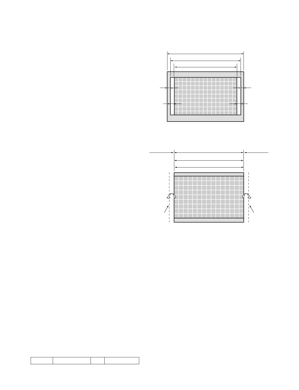
5. Turn the H SIZE SW in the menu to ON. Adjust H
SIZE so that the right and left sides of the raster can be
completely displayed. (Adjust A and A’ in Fig. 1-6 to
about 10 mm.)
6. Adjust the H. CENTER data so that the raster area
comes to the center of the effective screen (so that A
and A’ are almost equal). (Fig. 1-6)
When this adjustment is complete, take note of the H.
CENTER adjustment data.
7. Adjust the H. PHASE data so that the signal area
comes to the center of the raster area (so that B and B’
are almost equal). (Fig. 1-6)
When this adjustment is complete, take note of the H.
PHASE data.
8. Set the H SIZE SW in the menu to OFF, and return the
H SIZE to the original value.
9. Adjust the H BLK LEFT data so that the left edge of
the raster area comes outside of the left edge of the
cross-hatch signal area just before the effective screen.
Write the data calculated by subtracting ten steps from
that register to H BLK LEFT.
10. Adjust the H BLK RIGHT data so that the right edge
of the raster area comes outside of the right edge of the
cross-hatch signal area just before the effective screen.
Write the data calculated by subtracting ten steps from
that register to H BLK RIGHT.
11. Check the center of the image (image phase). If it is
misaligned, repeat steps 5 to 10.
12. H CENTER
H PHASE
H BLK LEFT
H BLK RIGHT
Copy the above-described data to the following modes.
13. Set BRIGHT to the normal position.
Fig. 1-6
Fig. 1-7
A’
B’
A
B
CRT effective screen
Raster area
Signal area
CRT effective screen
Outside the
effective screen
H_BLK
_LEFT
Raster area
Signal area
Outside the
effective screen
H_BLK
_RIGHT
MODE3 1035/60i (33kHz) 16:9 NORMAL