22
KV-25M2/25T2
(ON SCREEN
DISPLAY)
5
(DIGIT 5) (VOLUME -)
(TV)
i
+
Table 1
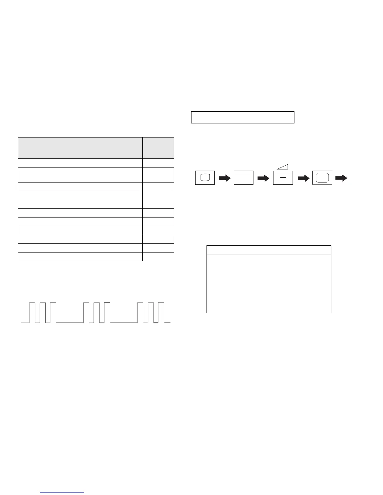
Flash Timing Example : e.g. error number 3
How to enter into Table 2
1. Turn on the main power switch of the TV set and enter into the
‘Standby Mode’.
2. Press the following sequence of buttons on the Remote
Commander.
3. The following table will be displayed indicating the error
count.
Table 2
Note: To clear the error count data press ‘80’ on the Remote
commander.
ERROR
LED
ERROR
COUNT
No error 00
Not allowed (may be confused with Sircs response
flash!)
01
Protection circuit trip < ANY TIME > 02
Reserved 03
No vertical sync 04
AKB 05
IIC bus clock and/or data lines low at Power ON 06
NVM no IIC bus acknowledge at Power ON 07
Jungle controller no IIC acknowledge at Power ON 08
Tuner no acknowledge at Power ON 09
Sound processor no acknowledge at Power ON 10
Error Times
2 -
3 -
4 -
5 -
6 -
7 -
8 -
9 -
10 -
4-3. FE-1 SELF DIAGNOSTIC SOFTWARE
The identification of errors within the FE-1 chassis is triggered in one of two ways :- 1: Busy or 2: Device failure to respond to IIC. In the event
of one of these situations arising the software will first try to release the bus if busy (Failure to do so will report with continuous flashing LED) and
then communicate with each device in turn to establish if a device is faulty. If a device is found to be faulty the relevant device number will be dis-
played through the LED (Series of flashes which must be counted) See Table 1., non fatal errors are reported using this method.
Each time the software detects an error it is stored within the NVM. See Table 2.