11
KV-34DRC430/36DRC430
KV-34DRC430/36DRC430
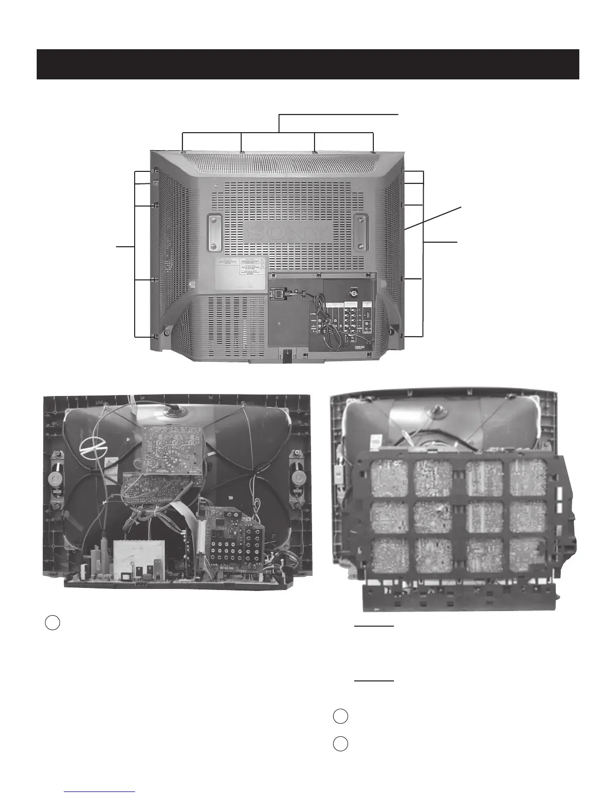
1-1. REAR COVER REMOVAL
SECTION 1: DISASSEMBLY
CAUTION! - Heat sink on IC5004 is -15V. Do not to allow
heat sink to touch GND or any other components.
Heat sink on Q8018 VpK=250V. Do not touch or short to
GND or other components.
CAUTION! - Pay attention to Neck Assembly WY Board
wire harness to BY Board. The WY Board can easily break if
there is sudden or excessive tension on the harness.
1
Lift lever up on the right and left sides of the chassis bracket
and gently pull the chassis assembly away from the bezel.
2
Pull up and rotate both the AY and DZ Boards in order to
service the unit.
1
Lift lever up on the right and left sides of the chassis
bracket and gently pull the chassis assembly away from
the bezel.
Rear Cover
5 Screws
+BVTP 4 x 16
TYPE2 TT (B)
1-2. CHASSIS ASSEMBLY REMOVAL
1-3. SERVICE POSITION
5 Screws
+BVTP 4 x 16
TYPE2 TT (B)
4 Screws
+BVTP 4 x 16
TYPE2 TT (B)