25
KV-34DRC430/36DRC430
KV-34DRC430/36DRC430
2-6.2. VIDEO INPUT - SUB HUE/SUB COLOR
ADJUSTMENT
Preparation:
• Input a Color Bar signal to VIDEO 1 (75 IRE 75%).
• Set picture mode: Single (Full) (PRO MODE Reset).
• Picture: Max
1. Set to Service Mode and adjust as follows:
NO. Name Control Function Avg. Data
01 RGBS R ON 4
2170P-2
2. Connect an oscilloscope to Pin 5 of CN9001 (B. DRV) on the CH
Board.
3. Adjust color according to Service Mode for SCLO.
4. Adjust color according to Service Mode for SHUO.
NO. Name Control Function
03 SCOL SUB-COL
04 SHUE SUB-HUE
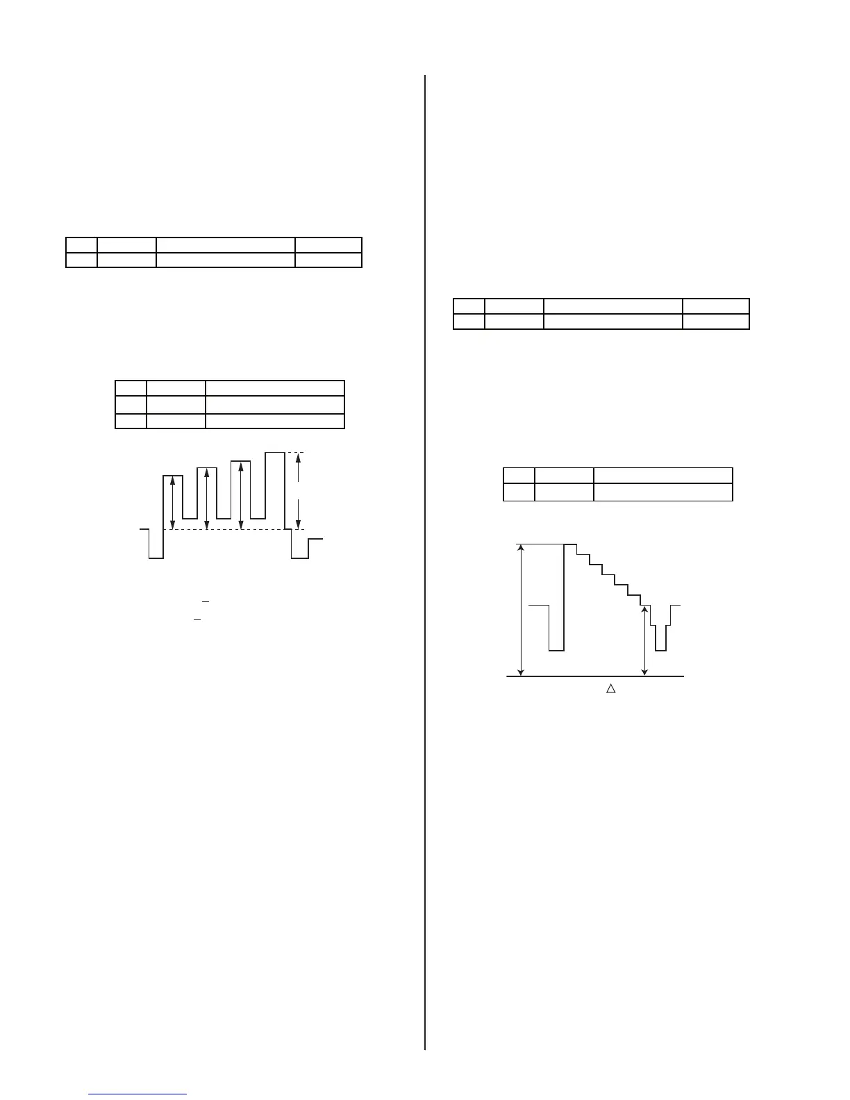
2103-1
VB4
VB3VB2VB1
COLOR: VB1 < VB4 (=20mV ± 200 mV)
HUE: VB2 < VB3 (=20mV ± 200 mV)
5. Write data into memory.
7
2-6.3. RF INPUT - SUB CONTRAST
ADJUSTMENT
Preparation:
• Input a Color Bar signal to RF (75 IRE 75%).
• Set picture mode: Single (Full) (PRO MODE).
• Picture: Max
• Color: Min
1. Set to Service Mode and adjust as follows:
NO. Name Control Function Avg. Data
01 RGBS R ON 4
2170P-2
2. Connect an oscilloscope to Pin 1 of CN9001 (R. DRV) on the CH
Board.
3. Adjust contrast according to service mode for SCON.
NO. Name Control Function
02 SCON SUB-CONT
2103-1
white
black
GND
VR2
VR1
VR
(34DRC) = 1.92 ± 0.05 Vpp
(36DRC) = 1.92 ± 0.05 Vpp
4. Write data from Step 3 above, into memory.