27
KV-34DRC430/36DRC430
KV-34DRC430/36DRC430
2-8. H RASTER CENTER ADJUSTMENT
Preparation:
• Input a monoscope signal.
• Set to NTSC (DRC) mode.
1. Set to Service Mode and adjust as follows:
NO. Name Control Function Data
05 AGNG AGING 1, AGING 2 2
NO. Name Control Function Avg. Data
02 HSIZ Horiz Size 34
01 HPOS Horiz Position 34
NO. Name Control Function Avg. Data
00 HBLK Blanking Enable 0
CXA2170P-2
CXA2170D-2
CXA2170D-3
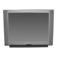
2. Reduce HSIZ to see sides of raster. (See Figure A)
3. Adjust H-Center with CXA2170D-2.
4. Adjust to the best screen position with H-CENT and write data.
5. Restore aging, HSIZ and HBLK to original condition.
Raster Edge Equal:
RASTER
EDGES
RASTER
Figure A
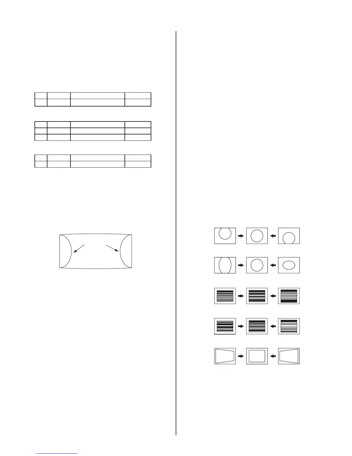
2-9. PICTURE DISTORTION ADJUSTMENTS
2-9.1. NTSC (DRC) FULL MODE
ADJUSTMENT
1. Face the picture tube in an east-west direction. (For best condition.)
2. Input a monoscope and crosshatch signal.
3. Adjust the picture distortion with these two signals to balance the best
condition between the two.
Use the CXA2170-D1 and -D2 adjustable data items shown here.
4. Complete V-PIN and V-CEN adjustments fi rst and adjust HPTZ to
straighten and parallel top and bottom lines.
5. Adjust VSCO, VLIN as necessary.
6. Adjust VSIZ and VPOS and write the data.
7. Adjust for Vertical line distortion.
8. Adjust VANG, VBOW, LANG, LBOW. Keep LANG and LBOW data
between 5 and 58.
9. Finish with UCP, LCP, PPHA, PIN adjustments. Check SLIN, MPIN.
10. Adjust for correct HSIZ and HPOS and write the data before
changing modes.
Note: Make sure that the picture size is within specs. Vertical size is
11.8 ± 0.1 sq. and horizontal size is 15.8 ± 0.1 sq.
.
CXA2170D-1
Item 0. VPOS (V-POSITION)
Item 1. VSIZ (V-SIZE)
Item 3. VLIN (V-LINEARITY)
Item 4. VSCO (V S-CORRECTION)
Item 9. HTPZ (H-TRAPEZOID)