20
KV-34DRC430/36DRC430
KV-34DRC430/36DRC430
SECTION 2: SET-UP ADJUSTMENTS
1. Input white pattern from pattern generator. Set the PICTURE control
to maximum, and the BRIGHTNESS control to standard.
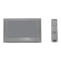
2. Loosen the defl ection yoke mounting screw, and set the purity
control to the center as shown below:
Purity Control
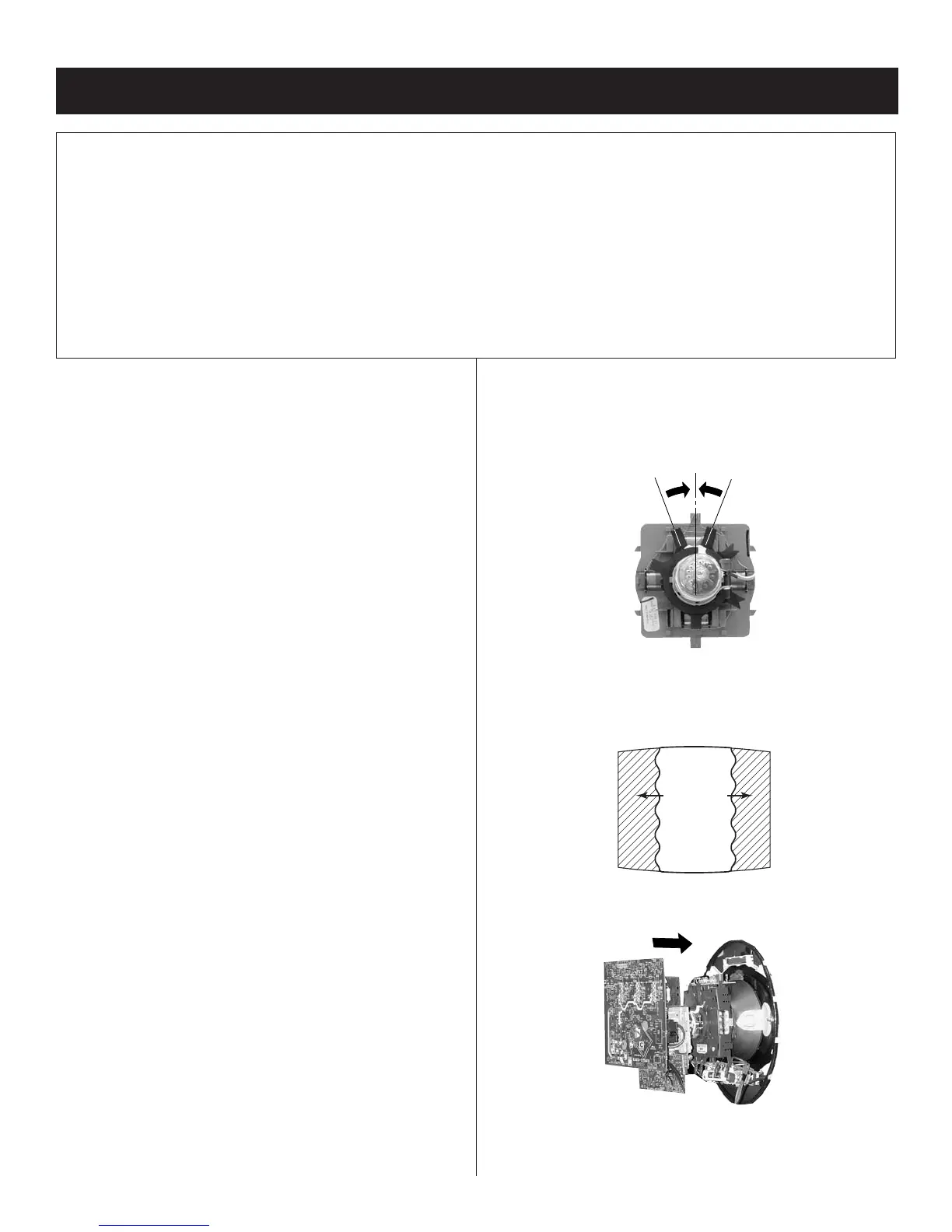
3. Input a green pattern from the pattern generator.
4. Move the defl ection yoke backwards, (See Figure 1) and adjust with
the purity control so that green is in the center and red and blue are
even on both sides.
Blue Red
Green
5. Move the defl ection yoke forward, and adjust so that the entire screen
becomes green.
2-1. BEAM LANDING
Preparation:
• Use cross hatch signal to rough adjust focus, G2 and then input a
white pattern signal.
• Face the picture tube in an East or West direction to reduce the
infl uence of geomagnetism.
• Remove all magnets, wedges, and permalogy strips.
• Confi rm data in service mode to match with CRT screen size.
•
Set 2170D-1 to their default settings.
• VCEN 31
• VPIN 15
• HTPZ 15
•
Set 2170D-2 to their default settings.
• PPHA 20
• VANG 31
• LANG 31
• VBOW 31
• LBOW 31
•
Set 2170D-4 to their default settings.
• CXA8070 to their default settings.
•
Set all user compensations to their default settings.
•
Set landings to their default settings.
• LT Left Top LCC Control 127
• LB Left Bottom LCC Control 127
• RT Right Top LCC Control 127
• RB Right Bottom LCC Control 127
NOTE: Do not use the hand degausser; it magnetizes the CRT
The following adjustments should be made when a complete
realignment is required or a new picture tube is installed.
These adjustments should be performed with rated power supply
voltage unless otherwise noted.
The controls and switch should be set as follows unless otherwise
noted:
VIDEO MODE: STANDARD (RESET)
Perform the adjustments in order as follows:
1. Beam Landing
2. Convergence
3. Focus
4. Screen (G2)
5. White Balance
Test Equipment Required:
1. Color Bar Pattern Generator
2. Degausser
3. DC Power Supply
4. Digital Multimeter
Figure 1