24
KV-34DRC430/36DRC430
KV-34DRC430/36DRC430
2-5. SCREEN(G2)
1. Input composite white fi eld into Video 1.
2. Set to service mode and adjust as follows:
(Fig. 1) Opeartion Procedure Standards Notes
1) In Full mode, apply changes in Fig. 1
CXA2170P-2 PICO 1-> 0
2) Mount G2 adjustment jig. Adjust Cathode
170 +/- 5 (V
DC
)
voltage if the standard is not met. Standard 34RSN, 36RV2
varies by CRT size.
175 +/- 5 (V
DC
)
3) Adjust G2 by Flyback transformer (T8001).
4) Return data changes in 1) to original condition.
2-6. PICTURE QUALITY ADJUSTMENTS
Preparation:
• Set PRO MODE (Reset).
1. Input signal (480i Composite):
• Color Bar Video 75 IRE (White) 75% modulation 7.5% Set-up.
• Color Bar RF 75 IRE (White) 75% modulation 7.5% Set-up.
2-6.1. VIDEO INPUT - SUB CONTRAST
ADJUSTMENT
Preparation:
• Input a Color Bar signal to VIDEO 1 (75 IRE 75%).
• Set picture mode: Single (Full) (PRO MODE Reset).
• Picture: Max
• Color: Min
3. Change CXA2170-P2 item 2 RGBS to 2 to make green only.
1. Overfocus to adjust DQP phase. Adjust the data
(CXA2170-D4 item 8) to balance left and right vertical line width.
2. Once DQP is balanced, remove the short from DF circuit and
refocus the set.
3. Adjust DF (CXA2170-D4 item 7) to balance left and right vertical
line width.
4. Reconfi rm focus performance.
34DRC 36DRC
QPAM 25 45
QPAV 40 47
QPAP 6 6
QPDC 17 42
QPDV 52 63
QPDP 6 6
DF 36 36
DQP 37 37
Table 1
1. Set to Service Mode and adjust as follows:
NO. Name Control Function Avg. Data
01 RGBS R ON 4
2170P-2
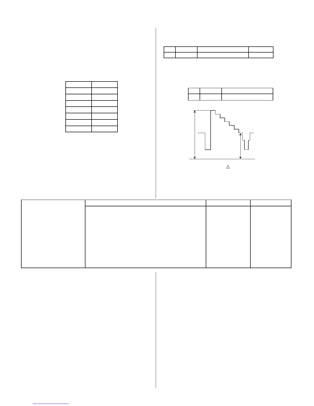
2. Connect oscilloscope to Pin 1 of CN9001 (R.DRV) on the CH Board.
3. Adjust contrast according to the service mode item: SPIO.
NO. Name Control Function
02 SCON SUB-CONT
2103-1
white
black
GND
VR2
VR1
VR
(34DRC) = 1.92 ± 0.05 Vpp
(36DRC) = 1.92 ± 0.05 Vpp
4. Write data from Step 3 above, into memory.