Sorensen DLM-E Series Advanced Operation
Operation Manual
29
Pin No. Function Pin No. Function
1
Remote Output Enable
1 = Enable, 0 = Disable
14
Remote Shutdown Input (+). Positive or
negative true logic selection with S1
2 Remote Shutdown Return (–) 15 +5 VDC Aux. Output
3 Remote OVP Programming Input 16
1 mA current source for OVP
Programming
4
Remote Programming Indicator
1 = Remote, 0 = Local
17
OVP Status Indicator
1 = OVP Shutdown, 0 = Normal
5
Operating Mode Indicator
1 = Volt mode, 0 = Current mode
18
Overtemp Shutdown Indicator
1 = OTP Shutdown, 0 = Normal
6 Status Indicator Return (–) 19 DC Voltage Monitor Output
7 Current Monitor Output 20 Remote/Local Voltage Control Select
8 N/C 21
1 mA current source for Voltage
Programming
9 Voltage Programming Input 22
1 mA current source for Current
Programming
10 Current Programming Input 23 Remote/Local Current Control Select
11 N/C 24 N/C
12 Programming/Monitor Return (–) 25 N/C
13 N/C
Table 4–1. J3 Connector – Program, Control, and Monitor Description
(D–subminiature 25–Pin Female)
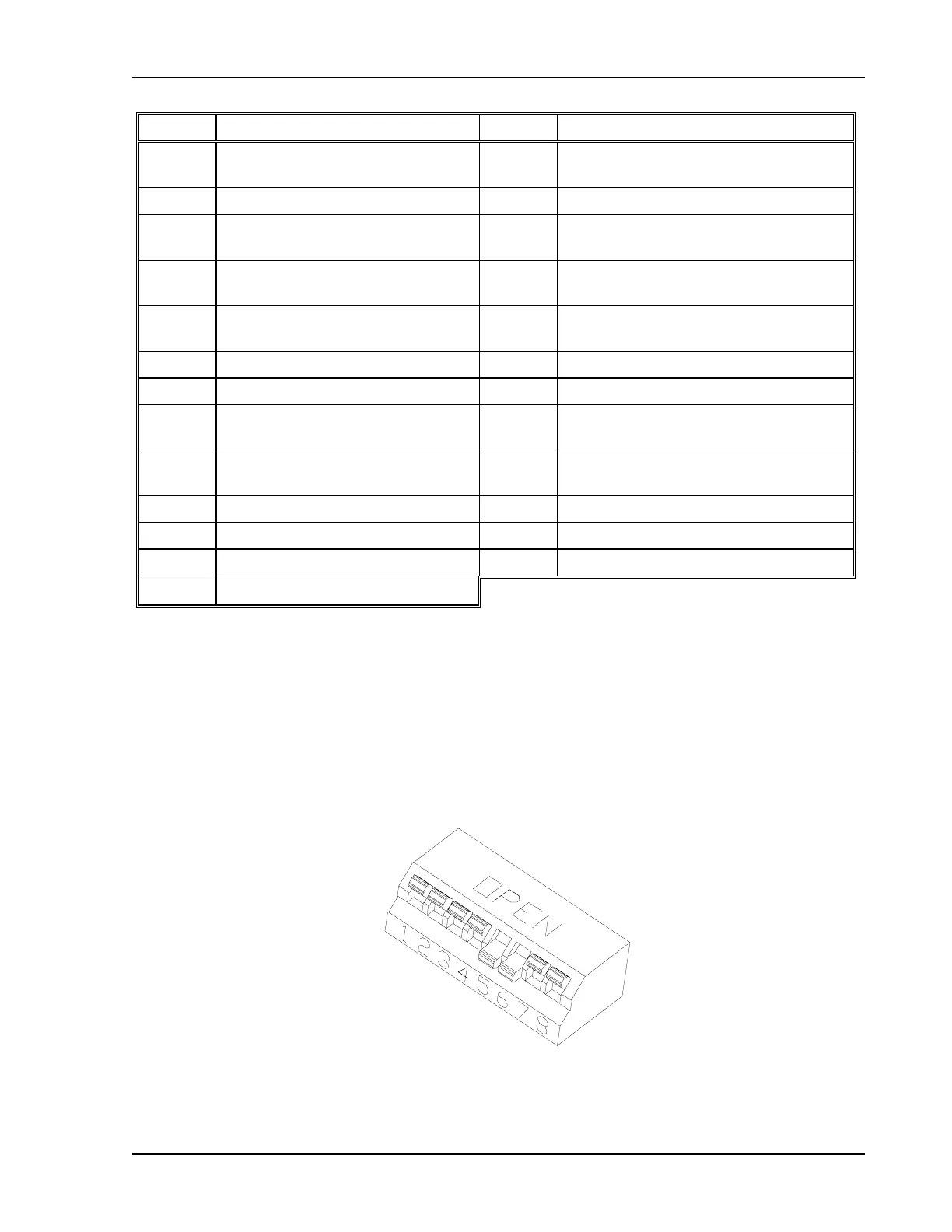
4.2.2 Rear Panel DIP Switch
Switch S1 is located on the main printed circuit board and is able to be changed through the
rear panel of the power supply. The J3 connector is located on the unit's rear panel. See
Section 4.2.3 Resetting Rear Panel DIP Switch Settings and Section 4.2.4 Making J3
Connections.
Figure 4–2. Locating Jumpers, Switch, and Connector