Maintenance and Troubleshooting Sorensen DLM-E Series
52 Operation Manual
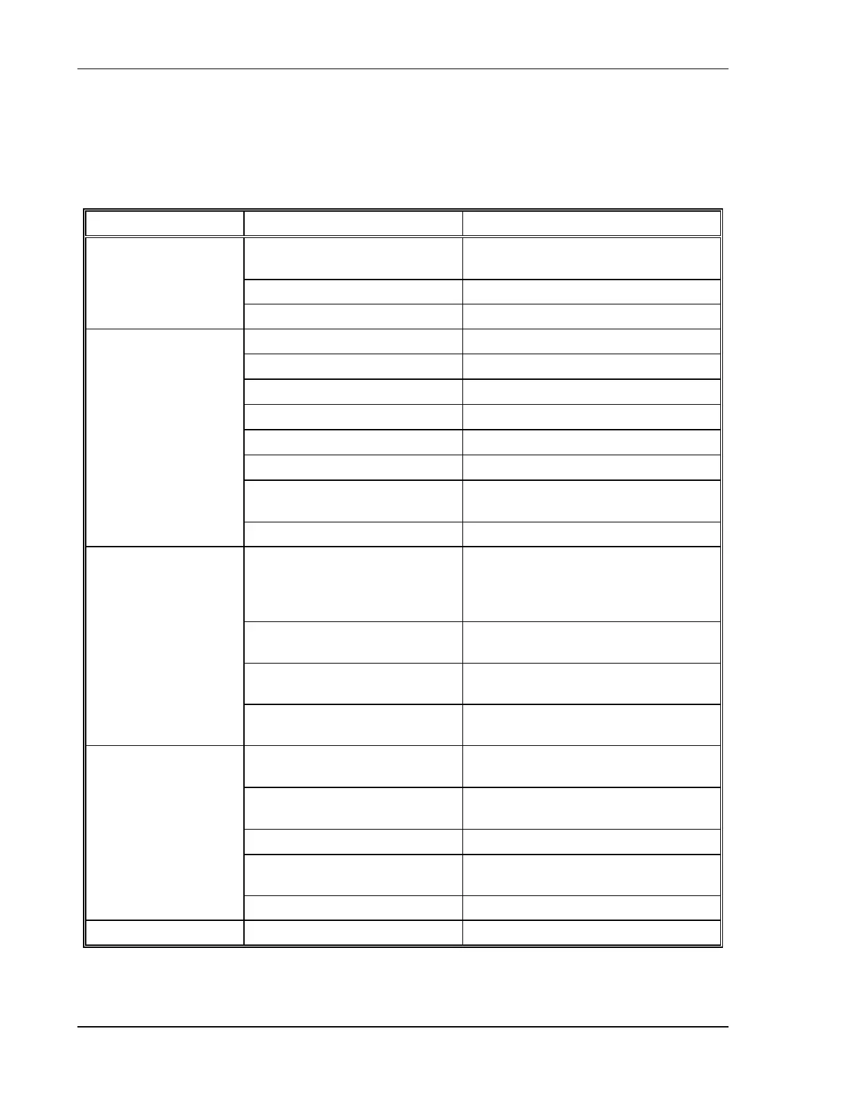
5.2.2 Troubleshooting at the Operation Level
Use the checks in Table 5–1 to ensure the DLM–E Series power supply is configured and
connected for default operation at the front panel. If you need any further troubleshooting, call
customer service.
Symptom Check Further Checks and Corrections
Is input voltage within specified
range?
Connect to appropriate voltage
source. See Section 2.6.
Power switch ON? Turn on power.
No output and the
display is blank
Internal circuit? See your service technician.
OVP LED lit?
See Section 2.4.1.
Front panel S/D LED lit?
See Section 2.4.1.
OTEMP LED lit?
See Section 2.4.1.
Current limit set to zero?
See Section 3.2.2.
Voltage control set to zero?
See Section 3.2.2.
REM LED lit?
See Section 4.3.
Is front panel ON LED lit? Connect unit to AC supply in specified
range. See Section 2.4.1.
No output but the
display lights
Internal circuit. See your service technician.
Is unit in current limit mode?
(Green Current Mode LED lit.)
Turn current knob clockwise to
increase current limit. Reduce load if
current is at maximum. See
Section 3.2.1.
Is unit in REMOTE mode?
(Green REM LED lit.)
See Section 4.3.
Is unit in LOCK mode?
(Green LOCK LED lit.)
See Section 4.8.
Output not adjustable
Is unit at maximum voltage or
current limit?
Reduce load for lower voltage or
current requirement.
Is unit at current limit? Increase current limit setting or reduce
load. See Section 3.2.1.
Is input voltage within specified
range?
Connect to appropriate AC voltage
source. See Section 2.6.
Are sense lines connected?
See Section 2.8 and Section 3.3.
Is unit under remote analog
control?
Ensure program source is stable.
Output voltage
fluctuating
or regulation poor
Internal circuit. See your service technician.
Output oscillating Internal circuit. See your service technician.
Table 5–1. User Diagnostics