BMK-8 U / BMK-12 W
36
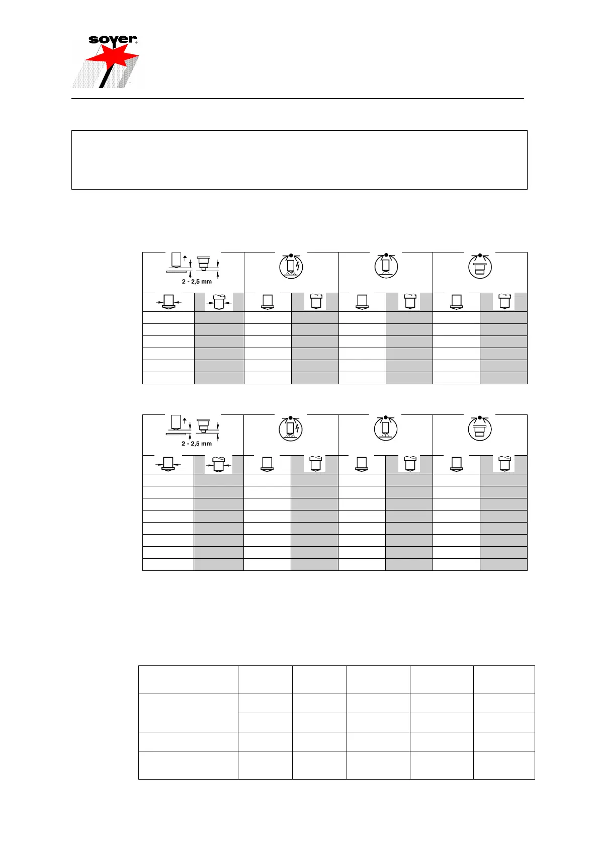
6.2 Welding parameters for welding operation
The set welding parameters influence the reproducibility and quality of the welding results to a large extent. The parameters
depend on the size of the studs and the material properties. The values indicated in the tables are standard values which are
exclusively valid for studs supplied by SOYER. They may vary depending on the type of workpiece, the workpiece thickness,
the surface condition of the workpiece and on environmental conditions (e.g. low outdoor temperatures). The settings of the
welding gun or welding head influence the welding parameters as well.
Random samples should be taken during any production process to ensure constantly good welding
results (see DIN EN ISO 14 555, "Arc welding of metallic materials")
Table for BMK-8U
Table for BMK-12W
When using stud diameters exceeding 6 mm, we recommend the application of shielding gas or
ceramic ferrules in order to prevent pore formation and to optimise bulging.
6.2.1 Minimum sheet thickness when welding with drawn arc operation
Observance of the minimum sheet thickness prevents the plate from being burnt through during the
welding process.
Drawn arc stud welding
with ceramic ferrule or
shielding gas
Short-cycle drawn arc
stud welding
Capacitor discharge
drawn arc stud welding
CF = ceramic ferrule, SG = shielding gas, NP = no weld pool protection