Maintenance
91369 Service Manual 4-16
Replacing the Connector PCBA
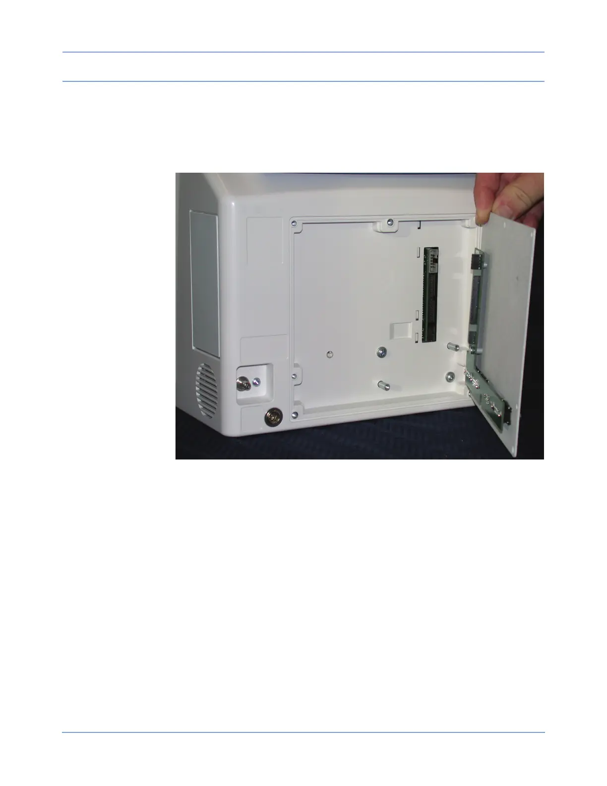
Removing the Rear Panel
1 Remove the five 6/32-inch × 1/2-inch screws.
Figure 4-9: Rear panel replacement
2 Remove the two 10/32-inch × 1/2-inch screws.
3 Carefully remove the rear panel and set it aside for further disassembly.
Removing the Connector PCBA
1 Remove the six 3/16-inch jack screws that secure the SDLC, video, and RS-232 connectors.
2 Remove the two 6/32-inch × 1/4-inch screws that secure the SDLC PCBA to the rear panel.
3 Reinstall the replacement connector PCBA in reverse order.
Replacing the CPU PCBA
1 Remove the batteries, if present.
2 Remove the bezel (refer to Removing the Bezel Assembly on page 4-11).
3 Remove the nine screws that hold the CPU PCBA to the chassis (refer to Figure 4-10).
 Loading...