91369 Service Manual 4-23
Maintenance
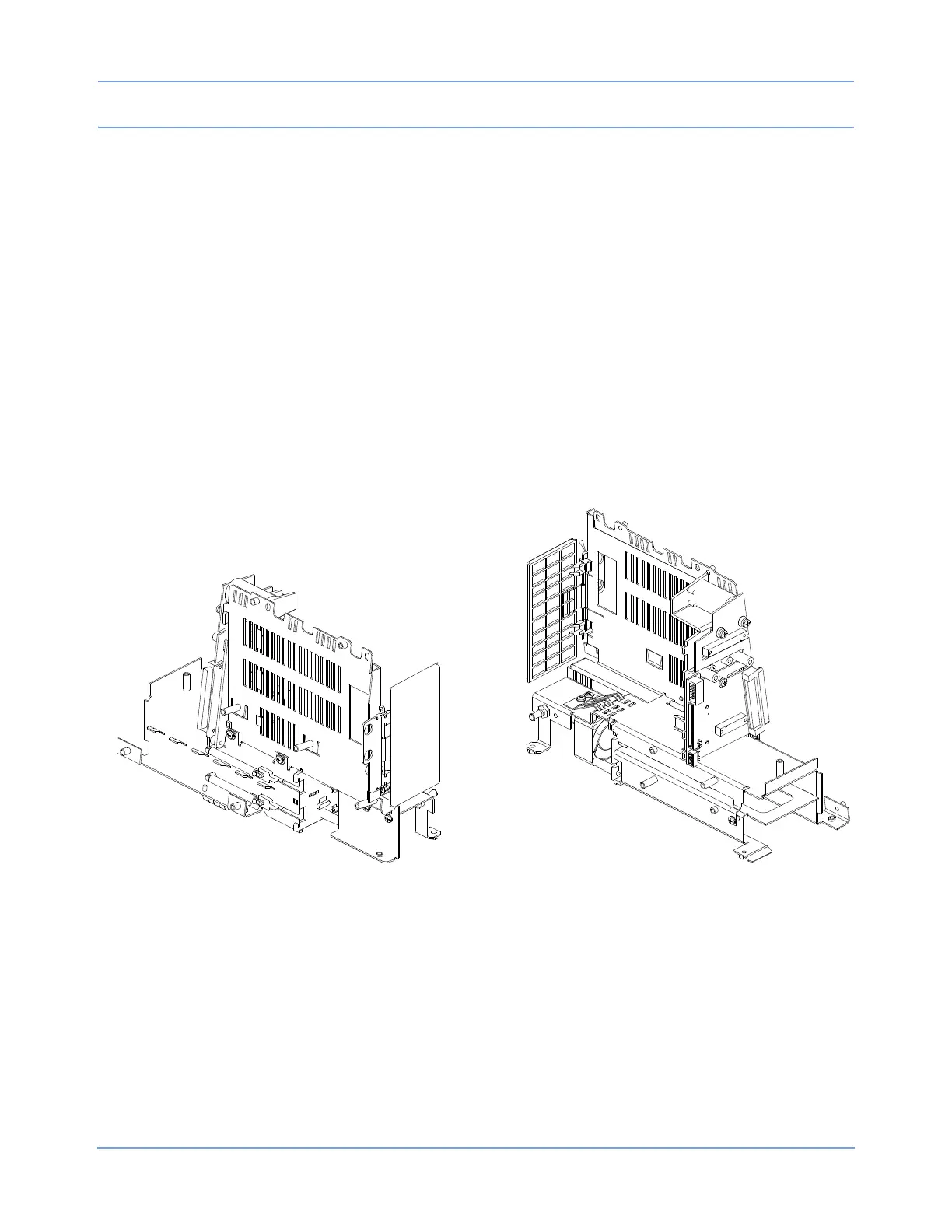
Replacing the Interconnect PCBA and Frame
1 Remove the chassis assembly from the housing as previously described.
2 Separate the chassis assembly from the module wall assembly by removing the two screws above the
battery ejection springs and the two screws near the bottom.
3 Remove the screw between the chassis and the Interconnect PCBA.
4 Separate the Interconnect PCBA and frame.
5 Reassemble the monitor in reverse order.
Replacing/Aligning the Module Door
1 To remove the door, remove the two nuts fastening the hinge to the wall of the module compartment
assembly. This will free the door assembly. When installing a new door, do not tighten the two nuts until the
chassis assembly is completely secured to the rear housing.
2 After the chassis and rear housing are mated, position the door and tighten the two nuts.
Figure 4-18: Module door
Replacing the Embedded Nurse Alert Assembly
1 Remove the front bezel carefully.
2 Slide out the embedded nurse alert LED assembly.
3 Reverse the procedure to install the replacement.
 Loading...