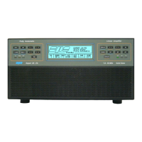
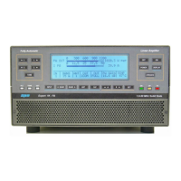
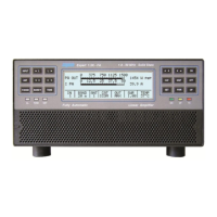
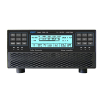
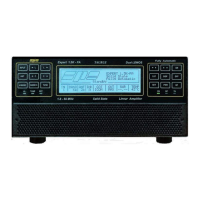
User manual EXPERT 2K-FA
Pag. 10 of 10 Issue 2 – May 2011
2. GENERAL INFORMATION
(Read the specific chapters for more details).
2.1 Power supply
The linear uses a switching power supply with a continuous input between 190 and 255
Vac.
The main switch [I/O] is located on the rear panel. In the [O] position all the internal
circuitry is powered off, in the [I] position (red led ON) it is possible to turn ON or turn
OFF the linear amplifier in one of the following ways:
a) Using the [ON]/[ OFF] keys on the front panel.
b) Applying / removing 9 -15 Vdc. on pin (8) of the CAT connector.
c) Using the USB port and the management software. It is possible to download
this software from the website www.linear-amplifier.com
.
Note: when turned ON, almost all transceivers output 13.8 Vdc. With this voltage, the linear
amplifier can be turned automatically ON / OFF at the same time as the transceiver.
2.2 Input / Output
The linear amplifier has two inputs (INPUT 1, INPUT 2) to which it is possible to connect
two transceivers of any brand or type.
These inputs are selected with the [INPUT] key or automatically with the PTT of each
transceiver.
It can manage up to six antennas (ANT 1, ANT 2, ANT 3, ANT 4, ANT 5, ANT 6).
The amplifier selects antennas automatically when they have been programmed.
The SO2R functionality is implemented using its own connector.
2.3 ALC / RELAY / CAT
There are two transceiver inputs (IN 1, IN 2), to allow two different transceivers to be
connected at the same time.
ALC is a voltage (0, -11 Vdc.) generated by the amplifier. It is used to control the
output power of the transceiver (max. in STANDBY”, the required in
“OPERATE”).
In this way the power from the exciter may be automatically regulated.
If the ALC port is not connected, it is necessary to manually regulate the
drive power from the transceiver.
This link is highly recommended.
RELAY This essential link allows the amplifier to be put in the transmit state. To do
that it is necessary that the inner pin of the phono connector is connected to
signal ground. This is normally done at the transceiver with either a “close-
on-ground” relay, or with a switching transistor. It is important that the
voltages at that terminal do not exceed 12 Vdc. On the transceiver this link is
often called SEND or TX GND. Refer to your transceiver manual for more
details.