User manual EXPERT 2K-FA
Pag. 42 of 42 Issue 2 – May 2011
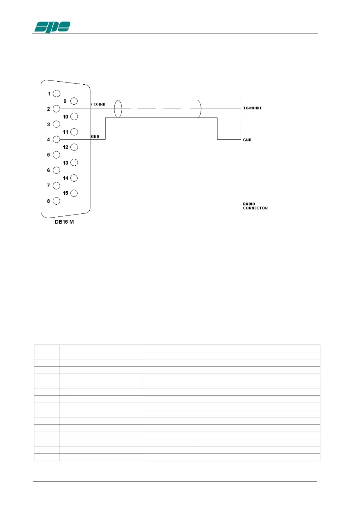
/TX-INH Link
Note: WARNING, SPE is not responsible for any failure resulting from misuse of HW
interface.
13.4 AUX Connector
This connector provides data on the bandwidth currently used in the two INPUT,
indicating which input is connected to the antenna ANT 1/2/3/4/5/6 and which is
connected to the SO2R,
In this way you can know which of the two transceivers is currently
connected to the output antenna set and when it is in transmission.
Pin n. Pin name Description
3 BIT A1 BIT A INPUT 1
5 BIT B1 BIT B INPUT 1
7 BIT C1 BIT C INPUT 1
9 BIT D1 BIT D INPUT 1
11 / EN 1 INPUT 1 0 = not connected with ANT, 1 = connected with ANT
13 / RLY 1 INPUT 1 0 = TX state 1 = RX state
1 GND GND
4 BIT A2 BIT A INPUT 2
6 BIT B2 BIT B INPUT 2
8 BIT C2 BIT C INPUT 2
10 BIT D2 BIT D INPUT 2
12 / EN 2 INPUT 2 0 = not connected with ANT, 1 = connected with ANT
14 / RLY 2 INPUT 2 0 = TX state 1 = RX state
2 GND GND
15 + 12 Vdc. OUT + 12 Vdc. 1 A max.