MZC-66 Hardware Installation Instructions Page 21
EZ-PAD CONFIGURATION
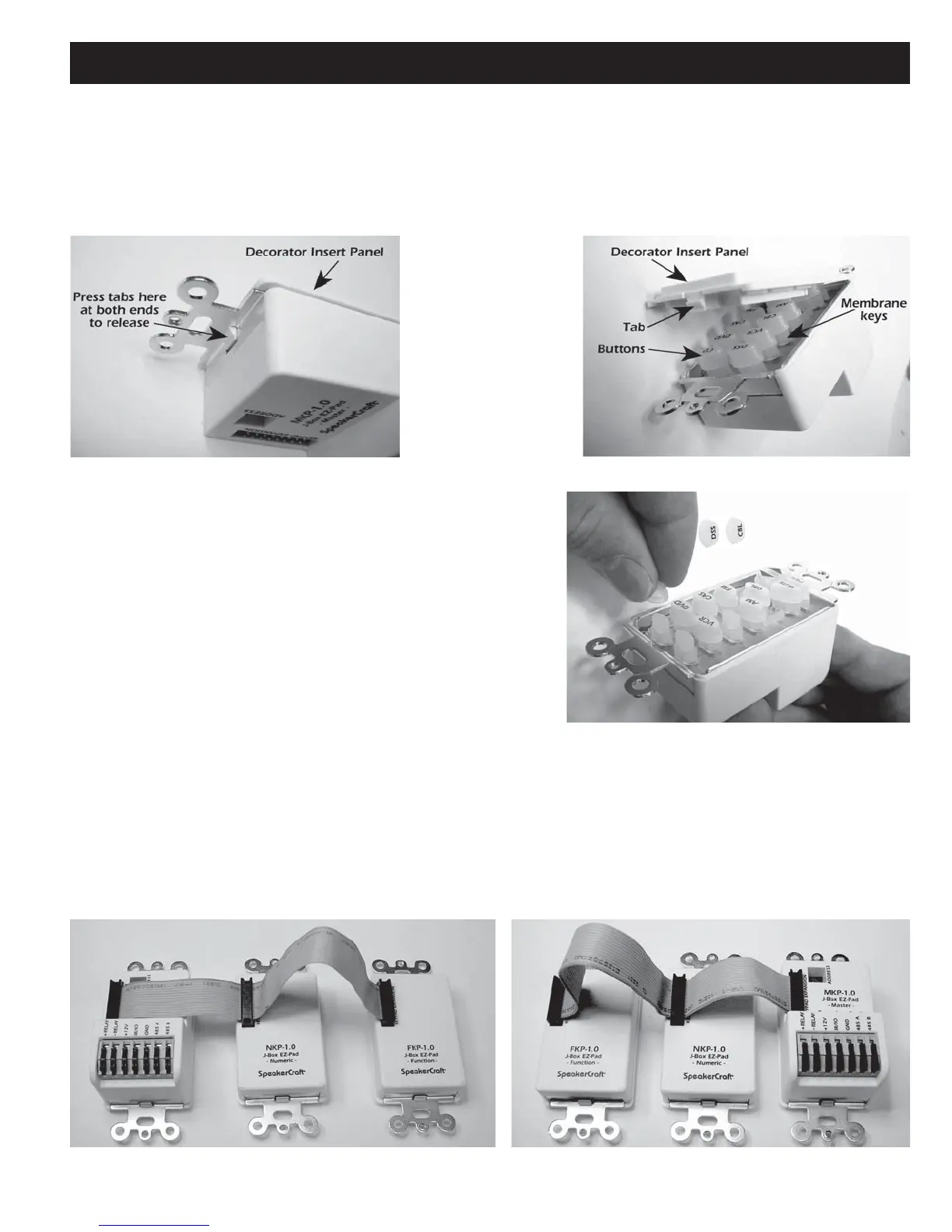
1. As received from the factory, the MKP-1.1 EZ-Pads have a preinstalled set of buttons that may not match the system
being installed. To change the source and function button arrangement, release the tabs, Figure 7, and remove the
decorator insert panel, exposing the key buttons. (Figure 8) IMKP and MODE 3.1 buttons can also be changed. See:
IMKP Installation Instructions and MODE 3.1 Installation Instructions for additional information.
Figure 8
Remove Decorator Insert Panel
Figure 7
Release Tab
2. Starting with the Zone 1 MKP-1.1 (Master Keypad), and using
the extra buttons supplied, if needed, move and place the
source and function buttons in an arrangement matching the
system being installed. (Refer to Figure 9) When finished,
replace the decorator insert panel over the buttons, being care-
ful to see that the buttons align correctly with the panel open-
ings. Press the panel down until the tabs “snap” into place.
3. Repeat these steps for each of the other zone Master Keypads.
Note that each zone can have its own unique configuration,
however, it is best to keep them as similar as possible to simplify
system programming and operation.
4. Repeat Steps 1-3 to configure the buttons on the Numeric and
Function keypads (not included) as needed.
NOTE: The Numeric and Function keypads will not work on their own. They must be connected to a Master Keypad
using the Ribbon Cable included with each NKP-1.0 and FKP-1.0. The cable is symmetrical so it can be connected
with the red striped side up or down, to best fit the configuration. Figure 10 shows it connected so that the MKP
Master Keypad will be to the right of the NPK Numeric and FKP Function keypads when mounted, whereas Figure 11
places the MKP to the left.
Figure 9
Moving and Placing Buttons
Figure 10
Ribbon Cable – MKP Right
Figure 11
Ribbon Cable – MKP Left

 Loading...


