MZC-66 Hardware Installation Instructions Page 37
COMMON STATUS OUT
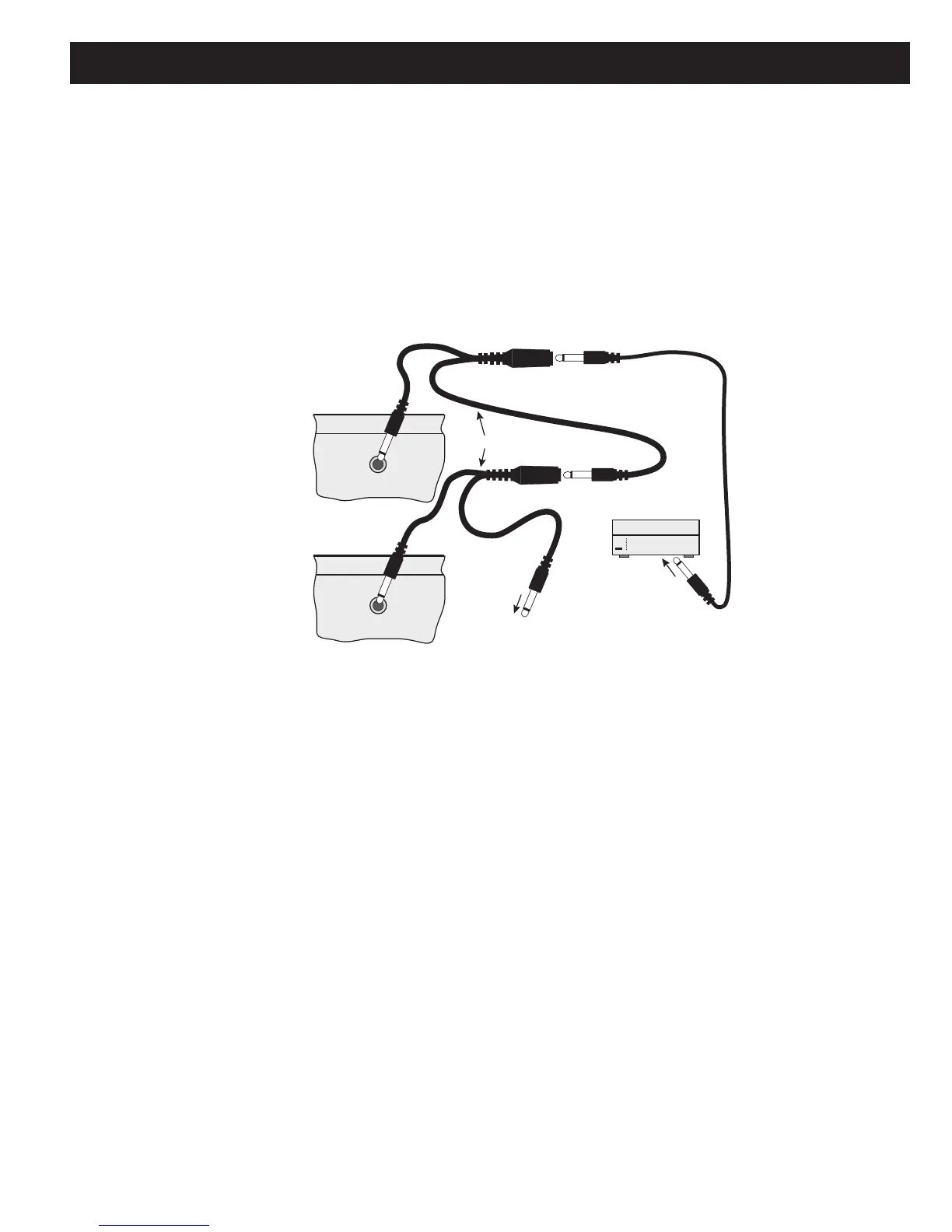
The Common Status Out jacks from multiple MZC-66s can be paralleled and looped using standard 3.5mm (
1
⁄8”) Y adap-
tors for 12 Volt DC control of a common device when any zone in the system is turned on.
NOTE: This application requires standard Y adaptors. DO NOT use the SpeakerCraft SAC-1.0 Y Adapter. The SAC-1.0
has ‘steering’ diodes that will interfere with the signal path in this application.
1. Daisy-chain the Y adaptors to the Common STATUS OUTS on all MZC-66’s in the chain as shown in Figure 22.
2. Connect a trigger wire to the Y adaptor assembly as shown in Figure 22.
3. Terminate the trigger wire as appropriate. Maintain proper polarity. Check connections prior to powering up the system
- Improper connection of a voltage trigger can damage system components.
4. Connect the trigger wire to the device to be triggered.
COMMON
COMMON
TO THE TRIGGER INPUT OF
A CONTROLLED DEVICE.
To Additional "Y" Connectors and
MZC's (Slaves #2 and #3) if needed
MZC
Master
MZC
Slave #1
3.5mm "Y" Cable Adapters
SpeakerCraft
®
To Trigger
Input
STATUS OUT
(0 to +12V)
STATUS OUT
(0 to +12V)
Figure 22
Common Status Out Expansion
RS485 BUS
In an Expanded System, when connecting MODE Base(s) and MODE Jukebox(es) or controlling RS232 devices, it will
be necessary to add at least one SpeakerCraft RSA-1.0 to create a RS485 bus from one of the MZC Expansion Ports. (Refer
to Figure 17) This will provide two-way communication with iPod(s) and Jukebox(es) for Serial Control to the devices and
metadata return to the MZC for display on MODE Keypads.
1. Connect one end of a CAT-5 Cable, terminated with RJ45 Connectors in a pass-through (pin to pin) confi guration to the
unused Expansion Port on the MZC-66 Rear Panel.
2. Connect the other end of the CAT-5 cable in Step 1 to the RSA-1.0 Expansion Port terminal.
3. Connect one end of another CAT-5 patch cable to the RSA-1.0 Expansion Loop terminal.
4. Connect the other end of the CAT-5 cable in Step 3 to the Expansion Port on the MODE Adapter as shown in Figure
17.
NOTE: Up to 16 RSA-1.0s can be daisy chained for control of up to 16 RS232 devices. However, only the last RSA-1.0
Loop can be connected to the Expansion Port on a MODE Adapter.

 Loading...


