MZC-66 Hardware Installation Instructions Page 23
HEAD-END
The MZC-66, external source components, and additional amplifi ers will typically be installed at the System Head-End. They
can be mounted on shelves in a wall unit, entertainment center or closet, or rack mounted in a standard 19” rack mount
system. Source components such as DVD/CD players and VCR’s should be installed so the user has easy access for loading
discs and tapes.
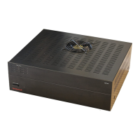
Though heavy, the MZC-66 (and additional amplifi ers if used) should be mounted at the top of the equipment rack so heat
generated by the controller will not affect the other system components. This will also allow cooler air to rise up through
the equipment rack with the hottest devices exhausting out the top. Use cooling fans such as the SpeakerCraft ESC-1.0 rack
cooling system, to push/pull air through the equipment rack if temperatures exceed the specifi cations of any of the system or
source components. Properly exhaust hot air into an attic space or outside the structure. (Be aware of and comply with any
building codes that may apply to ventilation.)
Always leave adequate space between system and source components for airfl ow. Failure to do so can cause damage to the
components from overheating. Never block the vent holes on the top or bottom of the MZC-66. Blocking the vent holes will
cause the controller to overheat. Never remove the MZC-66 Controller’s feet when shelf mounting. This will block the vent
holes on the bottom of the unit and will cause the controller to overheat. When using multiple MZC-66s in a system DO NOT
stack the MZC-66 Controllers directly on top of each other. Leave at least 3-4” between controllers, and if rack mounting, use
at least one, double rack-space vent panel between controllers to assure proper airfl ow.
INSTALLATION
CONNECTIONS - HEAD END
This section provides information for connections to a single MZC-66 Controller. See Section: Expanded Systems for infor-
mation on connections to multiple MZC-66’s in expanded systems. All system and source components should be installed
before making any connections. To prevent electrical shock and possible damage, be sure all components are disconnected
from AC power while making connections.
KEYPADS
1. Connect each keypad run to the appropriate EZ-Pad Terminal on the MZC-66. Be sure CAT-5 cable and RJ45 connec-
tors are properly confi gured as shown in Figure 12. See Sections: Wiring and EZ-Pad Confi guration for additional
information.
EXTERNAL SOURCE COMPONENTS
AUDIO/VIDEO
1. Connect the L & R line-level audio and COMPOSITE video OUT of each external source component to the appropri-
ate L & R line-level audio and composite video SOURCE IN on the MZC-66 Rear Panel. Use quality A/V RCA-RCA
cables with gold connectors.
EMITTERS (SOURCE)
1. Carefully attach a SpeakerCraft IR Emitter (Models: 1.0, 2.0, 3.0, 4.0) over the IR eye on the front panel of each exter-
nal source component to be controlled via infrared.
2. Carefully pull the emitter wire to the back of the MZC-66. Do not block accesses for discs and tapes. Do not pinch emitter
wires between components.
3. Connect the 3.5mm mini plug to the appropriate Source IR OUT.
SPEAKERS
1. Connect each Zone speaker run to the appropriate Zone Speaker Terminal using the included removable screw
down connectors.
2. Strip approximately
1
⁄4 inch of each lead and twist the stripped ends so there are no loose strands that can cause shorts.
3. Carefully slide the individual conductors into the appropriate L+,L-/R-,R+ speaker terminals on the removable screw
down connector.
4. Visually check for loose ends. Lightly pull the wire to confi rm connection.
5. Plug connector into the appropriate Zone Speaker Terminal.

 Loading...