SPECTRA SERIES 9
2.4 BACK UP BATTERY
In order to provide power during a power loss, connect a 12VDC 4Ah rechargeable acid/lead or gel cell backup battery as
shown in Figure 2-1A. Connect the backup battery after applying AC power. When installing verify proper polarity, as
reversed connections will blow the battery fuse. Also, refer to Battery Charge Current on page 41.
2.4.1 BATTERY TEST
If the battery is disconnected a "No/Low Battery" failure will appear in the keypads’ Trouble Display (see
page 54). This trouble will also appear if the battery’s capacity is too low or if the voltage drops to 10.5 volts
or lower while the control panel is running on the back up battery. At 8.5 volts or lower, the panel shuts
down and all outputs close.
2.5 AUXILIARY POWER TERMINALS
The auxiliary power supply terminals can be used to power motion detectors, keypads and other modules or
accessories in the security system. A fuseless circuit protects the power supply against current overload and
automatically shuts down if the current exceeds 1.1A. If this occurs the “Maximum Auxiliary Current” failure will appear
in the keypads’ Trouble Display (see page 54). Therefore, the combined current consumption of devices connected to
the auxiliary power supply should not exceed 700mA. If the auxiliary output is overloaded and is shut down, you must
disconnect all loads from the output for at least 10 seconds before reconnecting any load back to the auxiliary output.
2.6 TELEPHONE LINE CONNECTION
In order to report system events to the central station you must connect the incoming telephone company wires into
the TIP and RING connections of the control panel. Then run the wires from T1 and R1 to the telephone or
telephone system as shown in Figure 2-1A.
2.7 BELL OUTPUT CONNECTION
The BELL+ and BELL- terminals power bells, sirens and other warning devices requiring a steady voltage output
during an alarm. The bell output supplies 12VDC upon alarm and can support two 20-watt sirens or one 30-watt
siren. The bell output uses a fuseless circuit and will automatically shut down if the current exceeds 3A (1725,
1725EX, 1728, and 1728EX) or 2.5A (1758, and 1758EX). When this occurs the “Maximum Bell Current” failure will
appear in the keypads’ Trouble Display (see page 54). If the load on the BELL terminals returns to normal, the
control panel will re-instate power to the BELL terminals. When connecting sirens (speakers with built-in siren
drivers) please verify correct polarity. Connect the positive lead to the BELL+ terminal and the negative lead to the
BELL- terminal of the control panel as shown in Figure 2-1A.
If the BELL output is not being used, the "Bell Disconnected" failure will remain in the keypads’
Trouble Display (see page 54). To avoid this, connect a 1KΩ resistor across the BELL terminals.
Table 2: Current Consumption Table
Modules Current Consumption
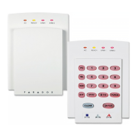
Spectra 1686H and 1686V 10-Zone LED Keypad 62mA typ. 116mA max.
Spectra 1689 16-Zone LED Keypad 50mA typ. 117mA max.
Spectra 1641 LCD Keypad 60mA typ. 80mA max.
SPC-319 Liberator
TM
Wireless Bus Expansion Module 70mA typ. 70mA max.
ZX8 8-Zone Hardwire Expansion Module 30mA typ. 30mA max.
SPC-ZX4 4-Zone Hardwire Expansion Module 12mA typ. 12mA max.
Motion Detectors (see detector instructions for details) 10-50mA typ.