SPECTRA SERIES 13
2.16 CONNECTING A LIBERATOR SPC-319 WIRELESS MODULE
The Liberator Wireless Bus Module (SPC-319) allows you to add up to eight fully programmable remote controls
and up to eight Liberator Wireless Detectors and/or Contact Switches (door contacts). For information on how to
program this module, please refer to page 47. (Not compatible with the Spectra 1758 and 1758EX.)
2.16.1 LOCATION
Mount the Liberator on a wall allowing at least 5 cm (2") around the module to permit adequate ventilation
and heat dissipation. Select a site that is not susceptible to drastic temperature changes. Avoid installation
near or in the path of strong RF fields (i.e. neon lights, computers), on or near metal objects, circuit breaker
boxes, air conditioners, and heater ducts since they may cause interference and reduce its sensitivity. We
recommend installing it in a centralized location on the main floor. Avoid installing it in the basement.
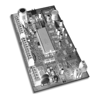
2.16.2 CONNECTIONS AND MOUNTING
Firmly screw the two antennas into the connectors marked "ANT" on the Liberator Wireless Bus Module as
shown in Figure 2-8. Using a drill or screwdriver, punch out the four mounting holes on the back of the
plastic case. Align the six holes of the printed circuit board with the six pins on the back plastic mounting
case and snap into place. If placed correctly, the antennas will lean directly over the grooves in the
mounting case. Connect the “
GRN
” and “
YEL
” terminals from Wireless Module to the corresponding “
GRN
”
and “
YEL
” terminals of the control panel. Connect the “
RED
” terminal to the “
AUX
+” of the control panel.
Connect the “
BLK
” terminal to the “
AUX
-” of the control panel.
The Liberator Module does not function with the Spectra 1758 and 1758EX.
Do not cut, bend, or alter
the antennas. Avoid mounting the Receiver Module near or on metal as this may affect its sensitivity.
Remove AC power and then remove the battery before adding a bus module to the system or it may
cause communication trouble.
Do not connect more than one Liberator Wireless Module to the panel.
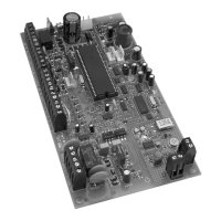
2.17 CONNECTING A ZONE EXPANSION MODULE (SPC-ZX4/ZX8)
The Zone Expansion Modules connect to the Spectra control panel's communication bus providing you with up to 4
(SPC-ZX4) or up to eight (ZX8) additional hardwired inputs and one 50mA on-board PGM output (ZX8 only). For details
on how to program these modules, refer to page 50. Connect the four terminals labeled
RED
,
BLK
,
GRN
and
YEL
of each
Zone Expansion Module to the corresponding terminals on the control panel as shown in Figure 2-9 on page 14.
Do not connect more than one Zone Expansion Module to the control panel. The ZX4 module is identical
to the ZX8 except there are no LEDs, there are only four zone inputs (Z1 to Z4) instead of eight and no
PGM output.
gure
-
:
era
or
re
ess
us
o
u
e
-