For Complete Warranty Information, contact Spectracom NetClock Wireless Clock System Instructions
www.spectracomcorp.com / US +1.585.321.5800 1168-5001-0050 Rev. H, Copyright June, 2011
Spectracom Corporation: 1565 Jefferson Road, Rochester, NY 14623 1 of 19
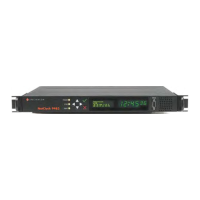
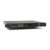
The Spectracom NetClock Wireless Clocks
are cost-effective facilities clocks that display synchronized time
across a campus, within a structure, or in a variety of other
installations. A Wireless Clock System comprises one or more
analog or digital display clocks, wireless transceivers, repeaters
(where required), and NetClock time server(s).
Once connected to a synchronized time source, the NetClock
Wireless Clock System transceiver transmits a signal to correct and
synchronize the time shown on the individual display clocks.
Spectracom Wireless Clocks synchronized in this manner should not
be set individually for this reason.
TABLE OF CONTENTS
1 INVENTORY AND INSPECTION 1-1
2 INSTALLATION 2-2
2.1 Install the Transceiver ................................................................................... 2-2
2.1.1 Connect Transceiver Power ................................................................... 2-2
2.1.2 Mount the Transceiver ............................................................................ 2-2
2.1.3 Make Necessary Connections ............................................................... 2-3
2.2 Configuring the Transceiver .......................................................................... 2-3
2.2.1 Configuring the Transceiver from the LED Display ................................ 2-3
2.2.2 Configuring the Transceiver from the Web UI........................................ 2-5
2.2.3 If Your Network Does Not Support DHCP ............................................. 2-5
2.2.4 Web UI Configuration ............................................................................. 2-5
2.3 Installing Antennas and Repeaters ............................................................... 2-6
2.4 Installing Digital Display Clock(s) .................................................................. 2-6
2.4.1 Synchronizing to the Transceiver ........................................................... 2-4
2.5 Installing Analog Display Clock(s) ................................................................ 2-4
2.5.1 Synchronizing to the Transceiver ........................................................... 2-4
2.5.2 Conserving Battery Power...................................................................... 2-4
2.5.3 Manually Transmitting and Receiving .................................................... 2-4
2.5.4 Testing the Distance Between Clocks Used as Repeaters ................... 2-4
3 CONFIGURING 6-DIGIT DIGITAL CLOCKS 3-4
3.1 Configuring Six-Digit Clocks Individually ...................................................... 3-4
4 TROUBLESHOOTING 4-6
4.1 Transceiver Troubleshooting Tips ................................................................ 4-6
4.1.1 Transceiver Will Not Synchronize to External Timing Reference .......... 4-6
4.1.2 Transceiver Does Not Power Up ............................................................ 4-6
4.2 Clock Troubleshooting Tips .......................................................................... 4-6
4.2.1 Digital Clock Does Not Receive Signal (Colon Blinking) ....................... 4-6
4.2.2 Digital Clock Does Not Power Up .......................................................... 4-6
4.2.3 Analog Clock Hands Do Not Move After Power-Up ............................... 4-6
4.2.4 Analog Clock Does Not Receive Signal ................................................. 4-6
4.2.5 Analog Clock Displays Incorrect Time ................................................... 4-7
4.2.6 Desire to Verify Analog Clock Signal Quality ......................................... 4-7
4.2.7 Signal to Desired Clock Location Receives is Marginal......................... 4-7
4.2.8 Distance Between Clocks is Too Great ................................................. 4-7
4.3 Analog Diagnostic 1 ...................................................................................... 4-7
4.4 Analog Diagnostic 2 ...................................................................................... 4-7
4.5 Analog Diagnostic 3 ...................................................................................... 4-7
LIST OF FIGURES
Figure 2-1: Line Cord Receptacle Installation .................................................................. 2-2
Figure 2-2: Rack-Mounting the Transceiver ..................................................................... 2-2
Figure 2-3: Transceiver Connections ................................................................................ 2-3
Figure 2-4: Login Screen .................................................................................................. 2-5
Figure 2-5: Successful Login ............................................................................................ 2-5
Figure 2-6: Technician-Level Menu .................................................................................. 2-6
Figure 2-7: Populating IP Address Fields ......................................................................... 2-6
Figure 2-8: Repeater Installation ...................................................................................... 2-6
Figure 2-9: Mounting Digital Display Clocks ..................................................................... 2-4
Figure 2-10: Digital Display Clock Wiring (4-Digit Typical) ............................................... 2-4
Figure 2-11: Digital Display Clock Wiring (6-Digit Units) .................................................. 2-4
Figure 2-12: Double-mounting Digital Display Clocks
...................................................... 2-5
Figure 2-13: Mounting Analog Display Clocks .................................................................. 2-4
Figure 2-14: Analog Display Clock Wiring, LEDs, and Switches ..................................... 2-4
Figure 2-15: Double-mounting Analog Display Clocks ..................................................... 2-4
Figure 3-1: Detailed Wiring for 6-Digit Digital Clocks ....................................................... 3-4
1
Inventory and Inspection
Before installing the Wireless Clock System, please verify that all
material ordered has been received. If there is a discrepancy, please
contact Spectracom Customer Service at US +1.585.321.5800.
Electronic equipment is sensitive to
Electrostatic Discharge (ESD).
Observe all applicable ESD
precautions and safeguards when
handling the Spectracom equipment.
NOTE: If equipment is returned to Spectracom, it must be shipped
in its original packing material. Save all packaging material
for this purpose.
Unpack the equipment and inspect it for damage. If any equipment
has been damaged in transit, please contact Spectracom Customer
Service at US +1.585.321.5800.
NOTE: The Wireless Clock System is not field-serviceable. If you
experience any problems with your display clocks,
repeaters, or transceivers, these components must be
shipped to Spectracom for service. Please contact
Spectracom at US +1.585.321.5800 before returning any
equipment and always ship the equipment in its original
packaging material.
NOTE: The range of the transceiver in unobstructed space is
approximately 2,000 meters; the range of the low-power
variant may be considerably less.
NOTE: This equipment has been tested and found to comply with
the limits for a Class B digital device, pursuant to Part 15 of
the FCC rules. These limits are designed to provide
reasonable protection against harmful interference in a
commercial installation. This equipment generates, uses
and can radiate radio frequency energy and, if not installed
and used in accordance with the instructions, may cause
harmful interference to radio communications. FCC
recommends a distance of 10cm from the clock to constant
human physical exposure.