For Complete Warranty Information, contact Spectracom NetClock Wireless Clock System Instructions
www.spectracomcorp.com / US +1.585.321.5800 1168-5001-0050 Rev. H, Copyright June, 2011
Spectracom Corporation: 1565 Jefferson Road, Rochester, NY 14623 2 of 19
2
Installation
Installing the Wireless Clock System consists of these steps:
1. Physically install the Clock Controller (transceiver) in your
equipment rack (Figure 2-1). Make all necessary
connections as shown in Figure 2-3.
2. Configure the transceiver at the unit or through the Web
User Interface. This includes configuring any external
timing references, such as NetClocks, to which the unit is
connected, either through Ethernet or through RS-485.
3. Install display clock(s) and synchronize the clock(s) to the
transceiver signal.
2.1
Install the Transceiver
The transceiver may be installed according to three possible facilities
scenarios:
Scenario 1: The transceiver has sufficient coverage for the
entire campus or structure. This means the
system does not depend on the display clocks for
transmission.
Scenario 2: In order to cover the entire campus or structure,
the display clocks (running on batteries) are used
as transceivers/repeaters to augment the
transceiver unit.
Scenario 3: In order to cover the entire campus or structure,
the display clocks (running on 110V, 220V, or 24V
power) are used as transceivers/repeaters to
augment the transceiver unit.
NOTE: Spectracom highly recommends installing the transceiver
before installing the display clocks. After installing the
transceiver, begin installing the clocks nearest to the
transceiver. Continue installing clocks, working from the
transceiver as the central point, until all clocks have been
installed and have corrected for the transceiver’s
transmitted time.
NOTE: A repeater is available from Spectracom. The repeater
receives and rebroadcasts a stronger wireless signal,
making it useful for bridging gaps between clocks.
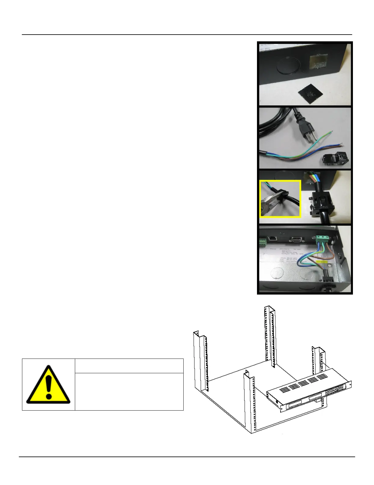
2.1.1 Connect Transceiver Power
Remove the rear cover. Prepare the power cord (Figure 2-1).
Installation personnel will need to punch out the appropriate access
hole in the transceiver chassis in order to make the connection.
Spectracom recommends the power supply
be connected by qualified personnel only.
Installation of the power cord by unqualified
personnel may cause injury or death and
will void the Spectracom product warranty.
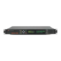
2.1.2 Mount the Transceiver
Mount the transceiver in your equipment rack using the Nylon
washers, the screws, and the threaded nuts supplied (Figure 2-2).
You may wish to make connections first. (A wall mount version of the
transceiver is also available. Drill and install as appropriate using the
equipment provided.)
Figure 2-1: Line Cord Receptacle Installation
Figure 2-2: Rack-Mounting the Transceiver
1. Remove the rear
cover of the chassis
and punch out the
square knockout.
2. Strip the power cord
wires and prepare
the plastic bushing
used with the power
cord.
3. Use pliers to install
the bushing, lettering
facing up, roughly
one inch from the
end of the power
cord insulation.
4. Connect the power
wires according to
the wiring diagram
found inside the
transceiver chassis.
The plastic bushing
the outside.