For Complete Warranty Information, contact Spectracom NetClock Wireless Clock System Instructions
www.spectracomcorp.com / US +1.585.321.5800 1168-5001-0050 Rev. H, Copyright June, 2011
Spectracom Corporation: 1565 Jefferson Road, Rochester, NY 14623 4 of 19
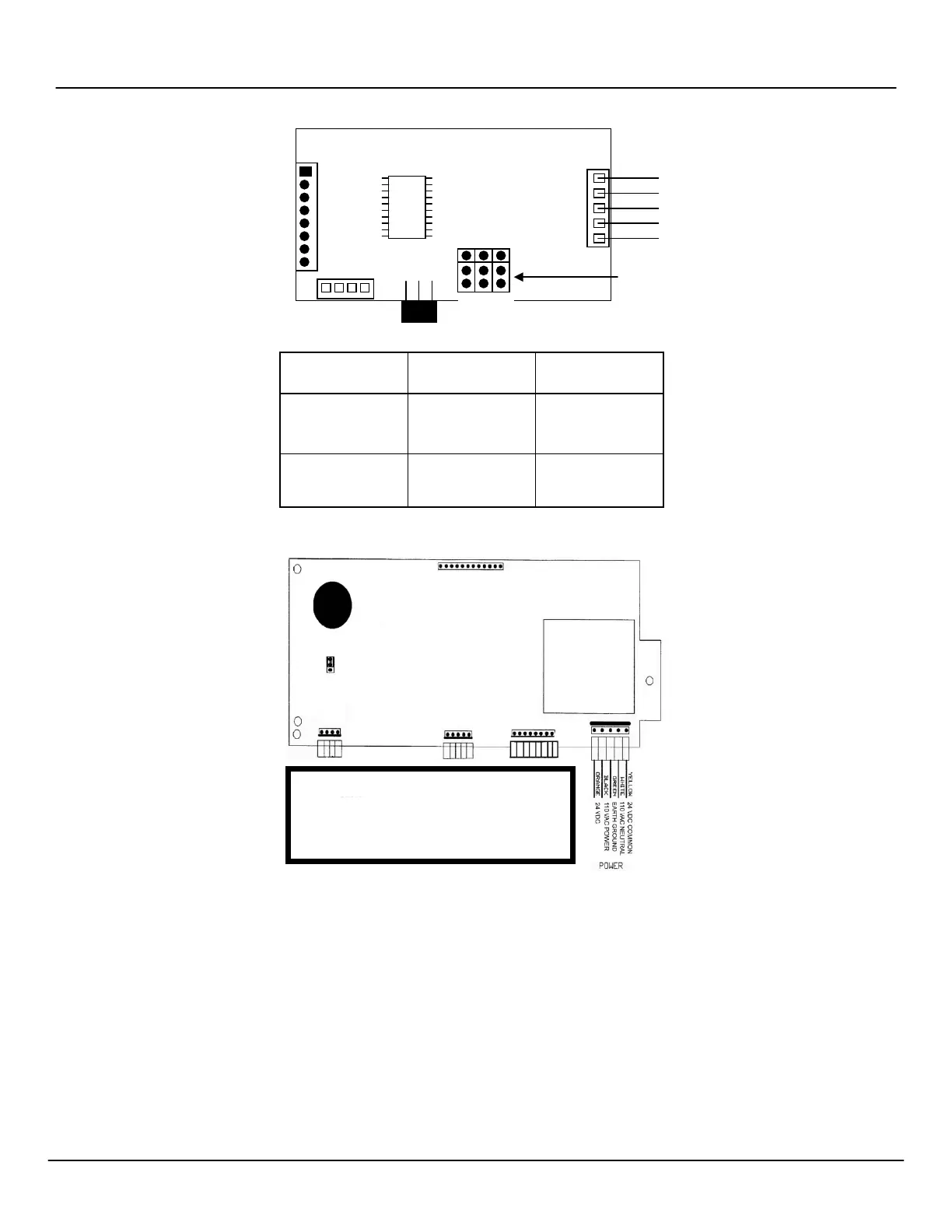
Figure 2-10: Digital Display Clock Wiring (4-Digit Typical)
Figure 2-11: Digital Display Clock Wiring (6-Digit Units)
Refer to the following section for an illustration of double-mounting digital displays.
P
P
P
3
Comm. Alert
OFF: 24 hour
mode
OFF: Less Bright
OFF: 30 minutes
110 Volts
BOX
NOTE: North American standard colors black,
green, and white for power, ground, and
neutral (respectively) correspond to
brown, green/yellow, and blue inter-
nationally.