For Complete Warranty Information, contact Spectracom NetClock Wireless Clock System Instructions
www.spectracomcorp.com / US +1.585.321.5800 1168-5001-0050 Rev. H, Copyright June, 2011
Spectracom Corporation: 1565 Jefferson Road, Rochester, NY 14623 4 of 19
Switch 1
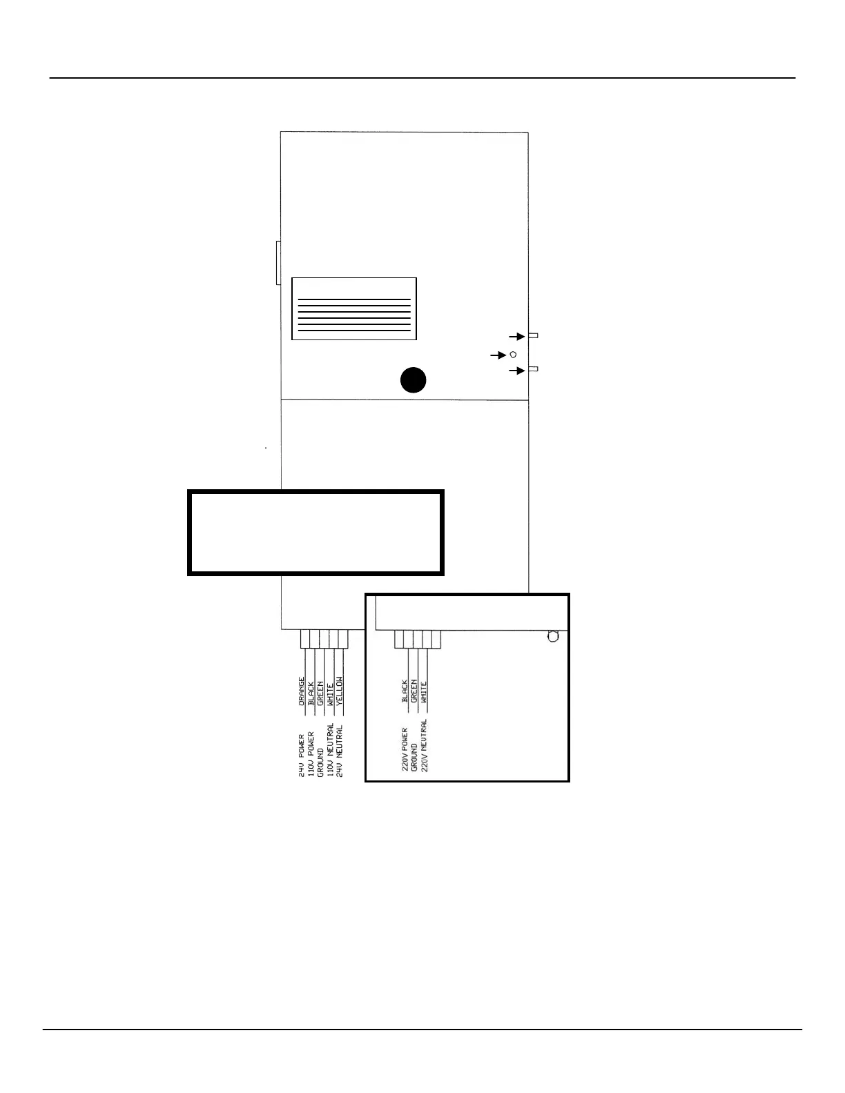
Figure 2-14: Analog Display Clock Wiring, LEDs, and Switches
Refer to the next section for information regarding double-mount installation of display clocks.
NOTE: North American standard colors black,
green, and white for power, ground, and
neutral (respectively) correspond to
brown, green/yellow, and blue inter-
nationally.
IRING
VARIATION
DIAGNOSTIC
TRANSMIT/RECEIVE