For Complete Warranty Information, contact Spectracom NetClock Wireless Clock System Instructions
www.spectracomcorp.com / US +1.585.321.5800 1168-5001-0050 Rev. H, Copyright June, 2011
Spectracom Corporation: 1565 Jefferson Road, Rochester, NY 14623 6 of 19
6.938 in.
17.6 cm
14.6 cm
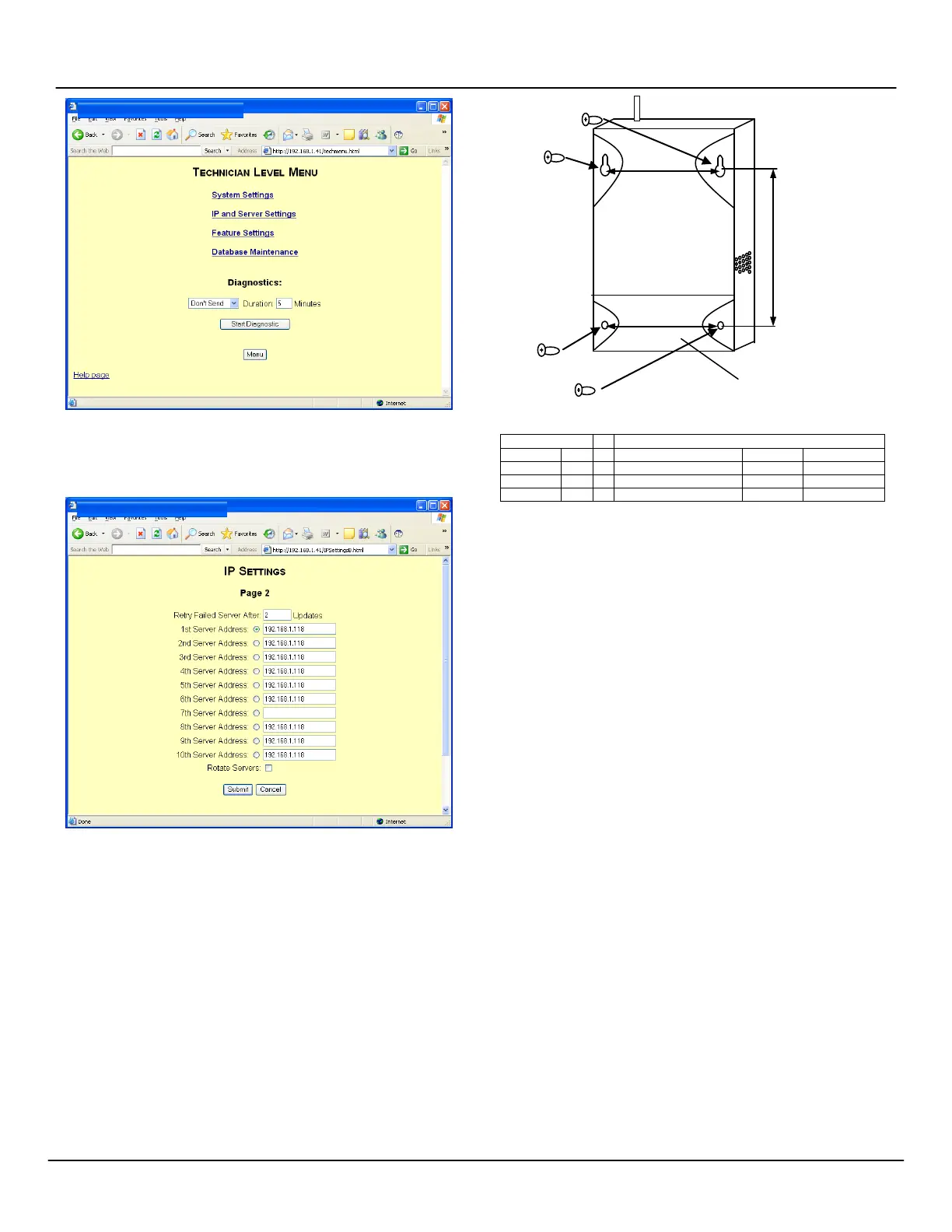
Figure 2-6: Technician-Level Menu
NOTE: When setting IP addresses (Figures 2-7) it may or may not
be necessary to repeat IP addresses in multiple fields.
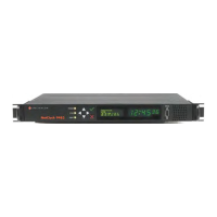
Figure 2-7: Populating IP Address Fields
NOTE: There may be many settings accessible through the Web
UI that you need not change for your application.
Whenever you are not certain of a value, leave it set to the
factory default. Contact Spectracom Customer Service at
US +1.585.321.5800 if you require further assistance.
2.3
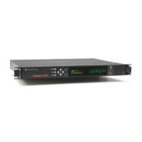
Installing Antennas and Repeaters
Antennas and repeaters are built using identical housings. Install
repeaters to cover gaps in signal coverage. Remove the cover of the
chassis, install physically as shown in Figure 2-8, and wire as shown
in the repeater wiring table. Set repeater jumpers JP1 and JP2 on
the bottom pair of each trio of pins. (The top pair of pins on the
jumpers are used when the unit is used as a transmitter.)
NOTE: 14 AWG is the smallest conductor acceptable for power
input.
Figure 2-8: Repeater Installation
REPEATER WIRING TABLE
2.4
Installing Digital Display Clock(s)
Display clocks can be wall-mounted (Figure 2-9) or double-mounted
(Figure 2-12). Spectracom recommends the following installation
procedure:
1. Wireless Clocks can be powered from a 24 volt source or
from a 110 volt source. For four-digit clocks, connect the
wiring as shown in Figure 2-10, setting the clock board’s
jumpers as required.
NOTE: For six-digit clocks, connect the wiring as shown in
Figure 2-11 and refer to Section 3 for clock configuration
and programming. Figure 3-1 includes detailed wiring.
2. Mount the wall mount box into the double gang box using
four machine screws.
3. Connect the ground wire into the flush mount box using a
tooth lockwasher and machine screw nut.
4. Disconnect the red filter from the display panel.
5. Complete the wiring connections as shown herein.
NOTE: For 24 volt installations, make sure the transformer is
ISOLATED.
6. Mount the display panel into the flush mount box using four
black machine screws. Make sure the switches are on the
right side.
7. Snap the red filter into the display panel.
NOTE: Wall-mounted clocks may also be mounted flush with the
wall surface.
To double-mount digital display clocks (Figure 2-12), Spectracom
recommends the following procedure:
1. Screw the hanger/mounting rod into the crossbar.
2. Insert the wires through hanger/mounting rod.