27
SECTION F.2.7
STANDARD TEST PROCEDURE FOR 5000 MV SINGLE
ELEMENT METER & METER CIRCUIT TESTING
(Save ONLY the GV SAVE Screen—For Forms 3, 4, 5, 6, 8, & 9 Meter Circuits and Meters)
1. Hookup Probes to Phase A (or B or C as appropriate) & Sensors to the Meter
1.1 Primary Current: Flex Coil--Arrow towards load, High Voltage--Large Dot Toward Line
1.2 Secondary Current: Duckbill / Copper side up
1.3 Secondary Voltage: Alligator Clips /Red to phase A (or B or C), Black to phase C
(Connect to phase C on the lug above the switch & leave it there for the entire test.),
and white to neutral/low side.
Exceptions: 1. Form 8-4 Wire Delta: Phase A--Red to phase A, Black to phase C, & White to
phase B. Phase B--Red to phase B, Black to phase C, & White to phase A. Phase C--Red to phase
C, Black to phase C, & White to phase neutral. 2. Form 4: Channel 1—Red to V1, Black not
connected, White to V2. Channel 2—Red to V2, Black not connected, White to V1.
1.4 Automatic Sensors: Attach the automatic sensors to the meter as shown in Section F.3.3.
1.5 Confirm Proper Voltage Wiring from the Test Switch to the Meter
(Skip this section if using Meter Base Adapters.)
1.5.1 Short phase B & C CTs and confirm the meter is reporting phase A
1.5.2 Short phase A & C CTs and confirm the meter is reporting phase B
1.5.3 Short phase A & B CTs and confirm the meter is reporting phase C
1.5.4 Close all CT shorting switches
2. Turn the Bird Dog Plus On
3. Enter Meter/Circuit/Rotation
3.1 If listed data is the same as your circuit: press YES and go to 4.1
3.2 If listed data is different than your circuit: press NO, select correct data and go to 4.1
3.3 If your circuit is not known or irrelevant: press UNDEFINED and go to 4.1
4. Enter LOCATION CODE
4.1 From LOCATION CODE screen press CHANGE button. Arrow points to first digit
4.2 Press the CLEAR button
4.3 Cycle the far left button 0-9, A-Z+ until the desired digit appears
4.4 Press the MORE button
4.5 Press NXT DIGIT. Arrow advances to next digit. Takes you back to previous screen
4.6 Repeat steps 4.3 through 4.6 until new location code entered
4.7 When the new location code is entered, press the MORE button twice
4.8 Press the SAVE to store new LOCATION CODE and go to the MAIN MENU
5. Review the WIRE VERIFY GRAPH for Input Signals
5.1 From the MAIN MENU select METER VERIFY TESTS
5.2 Select WIRE VERIFY GRAPH
5.3 Select PHASE A (or B or C)--Disregard PLS OR REV information on this screen
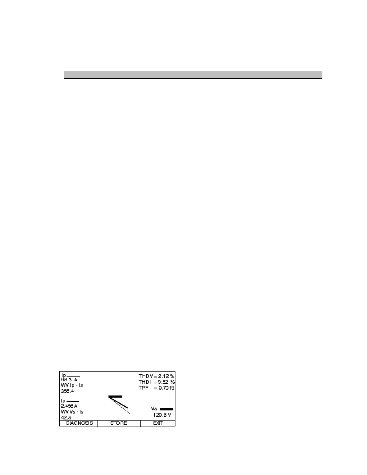
5.4 Review the readings as follows:
Secondary Voltage—OK? (Correct value, steady)
Secondary Current—OK? (>0.5 Amps, steady, balanced)
True PF—OK? (>0.7, steady)
Phase Angles—OK? (steady, adjust inherent phase shift)
THD Voltage--OK (<5.0%, steady)
THD Current--OK (<20.0%, steady)
Primary Current—OK? (>10% of rated ratio, steady