90
5000 MV ONLY!
Note: Ensure a .5 Amp Minimum on Each Conductor of a Form 2
Circuit--To test the .5 amp limit, go to the INSTANTANEOUS
READINGS screen and attach one of the CTs to one of the conductors.
Make sure the secondary current reading is .5 amps or greater. Repeat the
procedure for the second conductor. If both currents are greater than .5
amps then the accuracy of your test will be +/- .2%. Only one test is
required to test this form meter. Hookup the probes as follows:
Meter Test Hookup
Voltage Cable
o Red & Black Alligator clips to line 1
o White alligator clip to line 2. This produces V
12
or 240V.
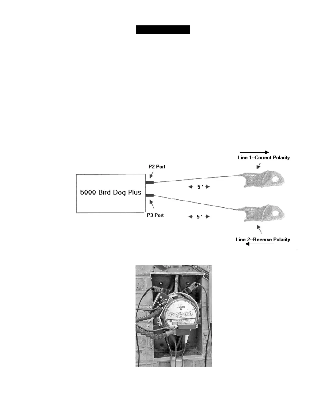
Clamp-on CT—From the P2 port around phase Line 1 arrow toward load
Clamp-on CT—From the P3 port around phase Line 2 away from load
(In the above illustration, a gray Y cable is connected to the P3 port for the sensors to attach.)
In the photograph above, the right clamp-on probe is correct polarity. The left probe is reverse
polarity.