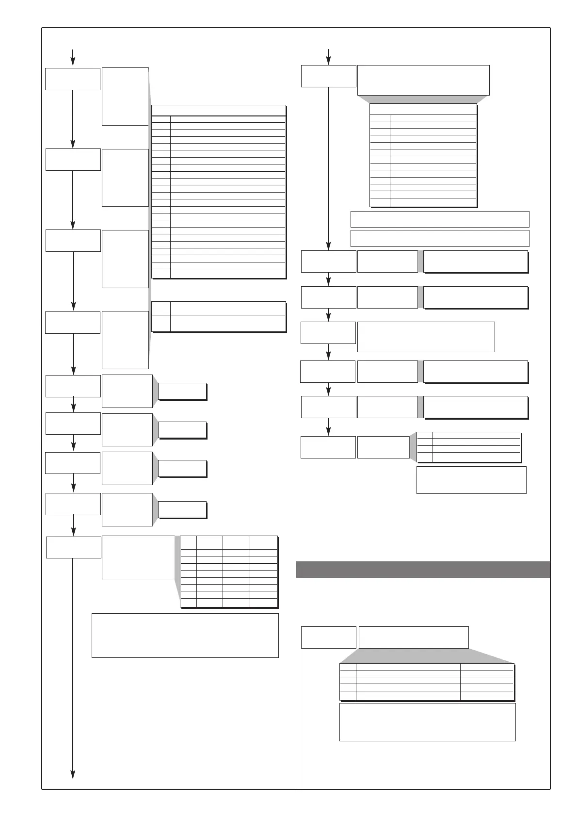
• Prot
an.o.1
l.an.1
x.an.1
an.o.2
l.an.2
x.an.2
at.ty
rl.o.1
rl.o.2
rl.o.3
rl.o.4
(t.1
(t.2
(t.3
(t.4
rel.
7
Fault action
(sets state in condition of
probe fault)
Alarm outputs AL1, AL2,
AL3; Select intrinsic safety
Minimum limit of the
analogue repetition
signal output 1
Note:
1) In case of broken probe, the logic state of the individual alarm takes
up the logic value assigned without taking into account the alarm type
(direct or inverse): ON=alarm active; OFF=alarm inactive
2) The assignment of the alarms to the available outputs is made by
entering codes in rLo1, rLo2, rLo3, rLo4.
Maximum limit of the
analogue repetition
signal output 1
Minimum limit of the
analogue repetition
signal output 2
Maximum limit of the
analogue repetition
signal output 2
An.o.x Reference value
0 PV - process variable
1 SSP - active setpoint
2 SP - local setpoint
3 InP.2 - auxiliary input
4 Deviation (SSP-PV)
5 HEAT (*)
6 COOL (*)
7 AL1 (alarm point)
8 AL2 (alarm point)
9 AL3 (alarm point)
10 AL.HB - (alarm point)
11 Value acquired from serial line
Out W1
Allocate signal or reference value:
PV, SP, SP-PROG, DEV+, DEV-, IN.AUX, HEAT,
COOL, AL1, AL2, AL3, serial line value
Out W2
Allocate signal or reference value:
PV, SP, SP-PROG, DEV+, DEV-, IN.AUX, HEAT,
COOL, AL1, AL2, AL3, serial line value
Allocation of
reference signal
to the Out1
output:
HEAT, COOL,
AL1, AL2, AL3,
input repetition
signal
Cycle time for AL3
relay or logic
output = HEAT or
COOL
67
68
69
70
74
75
76
77
78
79
80
81
_rEL Alarm Alarm Alarm
1 2 3
0 OFF OFF OFF
1 ON OFF OFF
2 OFF ON OFF
3 ON ON OFF
4 OFF OFF ON
5 ON OFF ON
6 OFF ON ON
7 ON ON ON
-100.0 ... 100.0% for power
-1999 ... 9999 for input and setpoint
An.o.1, An.o.2
1 ... 200 sec
+ 16 for inverted output with respect to the reference value
+ 32 for output with 2...10V, 4...20mA signal
(*) - Fixed scale limits
- Not available with ON/OFF control action
71
72
73
Cycle time for
Main relay or logic
output = HEAT or
COOL
Cycle time for AL1
relay or logic
output = HEAT or
COOL
Cycle time for AL2
relay or logic
output = HEAT or
COOL
1 ... 200 sec
(0.1 ... 20.0 sec)
1 ... 200 sec
1 ... 200 sec
Allocation of
reference signal
to the Out2
output:
HEAT, COOL,
AL1, AL2, AL3,
input repetition
signal
Allocation of
reference signal
to the Out3
output:
HEAT, COOL,
AL1, AL2, AL3,
input repetition
signal
Allocation of
reference signal
to the Out4
output:
HEAT, COOL,
AL1, AL2, AL3,
input repetition
signal
Valve Control
Type
0 disabled
1 V0, V1 Heating control
2 V2 Heating control
3 V3, V4 Heating control
+ 4 for Cooling control
+ 8 for Manual control of the valve with
“up” and “down” keys.
-100.0 ... 100.0% for power
-1999 ... 9999 for input and setpoint
-100.0 ... 100.0% for power
-1999 ... 9999 for input and setpoint
-100.0 ... 100.0% for power
-1999 ... 9999 for input and setpoint
rL.o.1, rL.o.2, rL.o.3, rL.o.4
+ 32 for inverse logic signal output
rL.o.x Function of main output relay/logic (OUT1)
0 HEAT (control output for heating)
1 COOL (control output for cooling)
2 AL1 - alarm 1
3 AL2 - alarm 2
4 AL3 - alarm 3
5 AL.HB - alarm HB
6 LBA - alarm LBA
7 IN1 - repetition of logic input 1
8 IN2 - repetition of logic input 2
9 Open valve
10 Close valve
11 -
12 Timer status repetition
13 Manual Set / Reset
14 (AL1) OR (AL2)
15 (AL1) OR (AL2) OR (AL3)
16 (AL1) AND (AL2)
17 (AL1) AND (AL2) AND (AL3)
18 (HBAL) OR (AL1)
19 (HBAL) OR (AL1) OR (AL2)
20 (HBAL) AND (AL1)
21 (HBAL) AND (AL1) AND (AL2)
64 Heat (control output with fast
cicle time) (*)
65 Cool (control output with fast
cicle time) (*)
(*) Only for rL.o.1, HB alarm disabled if
associated to Out 1
211
Prot
42
Protection code
Prot Display only Modification
0 SP, InP2, alarms, OutP, INFO, DATA SP, alarms, DATA
1 SP, InP2, alarms, OutP, INFO, DATA SP, alarms
2 SP, InP2, alarms, OutP, INFO SP
3 SP
+ 4 to disable InP, Out
+ 8 to disable CFG, Ser
+ 16 to disable SW “power up - power down”
+32 to disable manual power latching
+64 to disable manual power modification
-
-
-
-
-