IM-P343-35 CTLS Issue 5
29
SP500 Electropneumatic Smart Positioner
6.1 Guidance notes on wiring installation
For heavy industrial applications it is recommended to use screened cables or signal cables run in metal
conduit. Failure to do so could result in positional errors of up to ±5% in an RF field excess of 10 V/m. If
screened cables are used, ensure that the screen is connected to the local earth at one end with a connection
resistance of less than 1 ohm.
For light industrial applications where RF fields do not exceed 3 V/m unscreened cables may be used.
Cabling should be installed in accordance with BS 6739 - Instrumentation in Process Control Systems:
Installation design and practice or local equivalent.
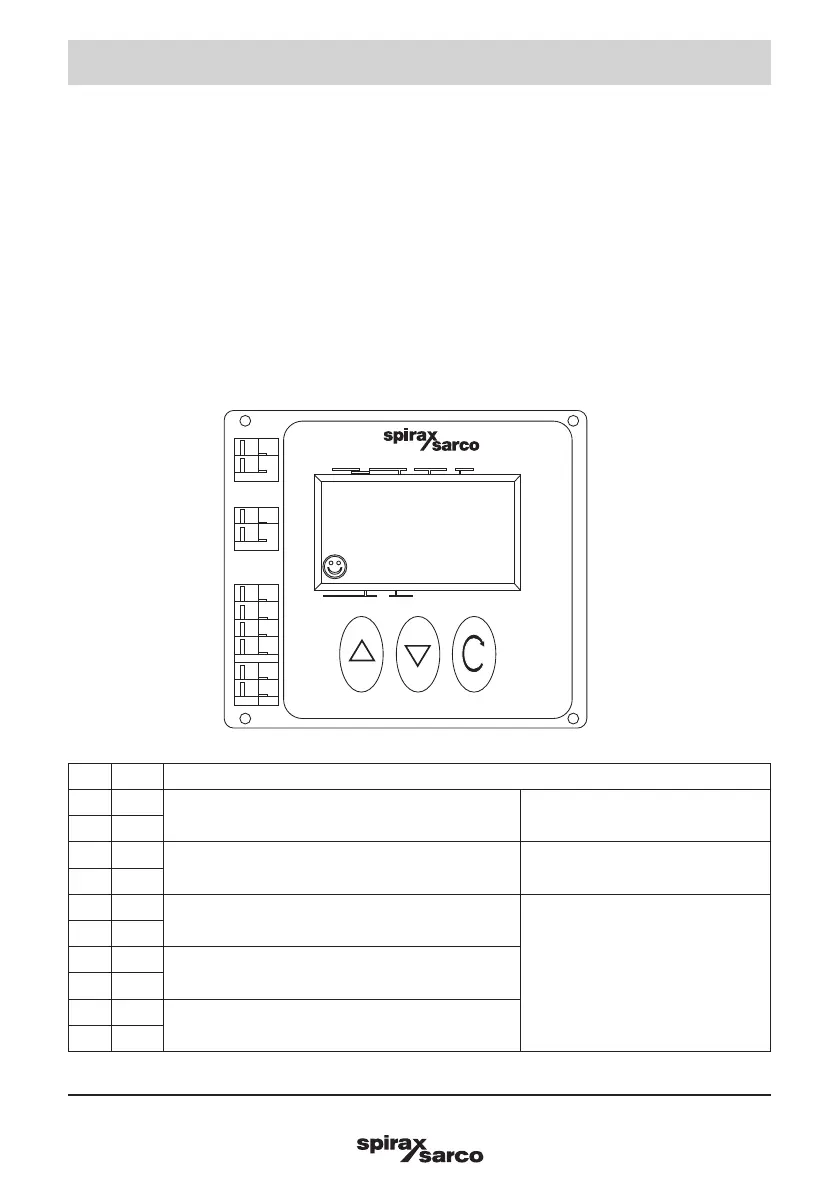
6.2 Wiring diagrams
6.2.1 Terminal block
No. Pole Description
1 +
24 V external power supply
24 V power supply option board
(PWS)
2 -
3 +
4-20 mA current signal input Mainboard
4 -
5 +
Travel switch 1
Retransmission and travel switches
option board (RTX)
6 -
7 +
Travel switch 2
8 -
9 +
4-20 mA retransmission of valve position
10 -
Fig. 46
SP500
AUTOMATIC
TUNE
50
%
SET
AUTOS
MANUAL
MENU
- +
RTX
- +
SW2
- +
SW1
- +
4-20mA
- +
24V
1
2
3
4
5
6
7
8
9
10
▲
▲
6. Electrical connections