IM-P343-35 CTLS Issue 5
11
SP500 Electropneumatic Smart Positioner
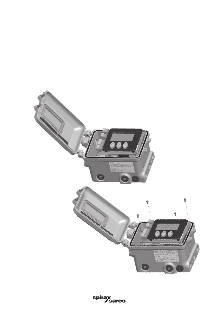
Fig. 4
Fig. 5
4.2 Retransmission and travel switches option board
An option b o a r d can be tted in t h e positioner to add valve po sition retrans m i s s i o n functionality and s o f t ware
travel switches functionality.
The board generates a 4-20 mA current signal which represents the actual valve position.
Moreover 2 output terminals are available to be congured as software travel switches.
The threshold can be adjusted via software.
Refer to Section 6, 'Electrical connections' for wirings.
Refer to Section 9.6.7 for travel switching conguration.
An option board is optionally available and can be mounted in situ. In this case please refer to the mounting
instruction below:
-
Open the positioner (Figure 4).
-
Switch o the power supply.
-
Switch o the air supply.
-
Unscrew the board as shown in Figure 5.