IM-P706-03 CTLS Issue 1
20
SP7-20 Smart Positioner
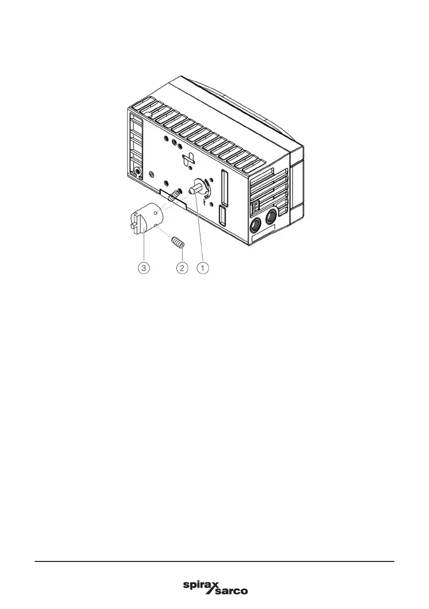
3.1.12 Mounting the adapter on the positioner
Fig. 13
1. Determine the mounting position (parallel to actuator or at 90° angle)
2. Calculate the rotational direction of the actuator (right or left).
3. Move the part-turn actuator into the home position.
4. Pre-adjust feedback shaft.
To make sure that the positioner runs within the operating range (refer to General on page XX), the
mounting position as well as the basic position and rotation direction of the actuator must be considered
when determining the adapter position on axis (1). For this purpose, the feedback shaft can be adjusted
manually so that the adapter (3) can be attached in the correct position.
5. Place the adapter in the proper position on the feedback shaft and fasten with threaded pins (2). One of
the threaded pins must be locked in place on the flat side of the feedback shaft.

 Loading...


