Software Sensor Timing
This setting, Timing Sensor °BTDC, will tell the software at what degrees the sensor is situated.
The ECU will calculate from this position where to advance or retard the timing to ensure that the
Map Timing is accurate with the actual timing on the engine.
In the PC software you must enter the Timing Sensor °BTDC for the specific distributor. If it has a
standard magnetic pickup it usually is around 24 ° BTDC. Note however that if you are converting
your distributor then a 0 or 1 ° fazing for the sensor is preferable.
To check if this setting is correct disconnect the injector fuses and crank the engine with a timing
light. See if the light flahes between 5 and 10°. If not adjust the value till it does.
Now you can start the engine. It should start easy and run smoothly. Should the engine tend to
stop during cranking, it means the timing is too fast. Increase this value 10° at a time. Should it
sound as if it wants to start but dies, it means that the timing may be too slow. Decrease this value
10° at a time. If there is a misfire of any sort, stop immediately and do faultfinding. It may be that
the magnetic pickup is wired wrong causing the spark to fire between the poles. If it is a hall or
optic sensor the timing edge may be wrong. See edge setting under active sensors.
After the engine has started, check with a timing light that your engine timing correlates with the
software timing block. If not adjust the Timing Sensor °BTDC value until they match. Now perform
a normal timing adjustment according to the PC timing on the timing maps. Note that adjustable
timing light can be misleading on wasted sparks system. Divide the timing light degrees by two.
Listen for spark in the distributor cap. If you hear a spark then the fazing degrees are wrong and
there is a gap between rotor and pole. An old cap with a hole across one of the poles can be used.
Flash the timing light into the hole to check for correct rotor position. Incorrect fazing will also hang
the Laptop and freeze the PC Software.
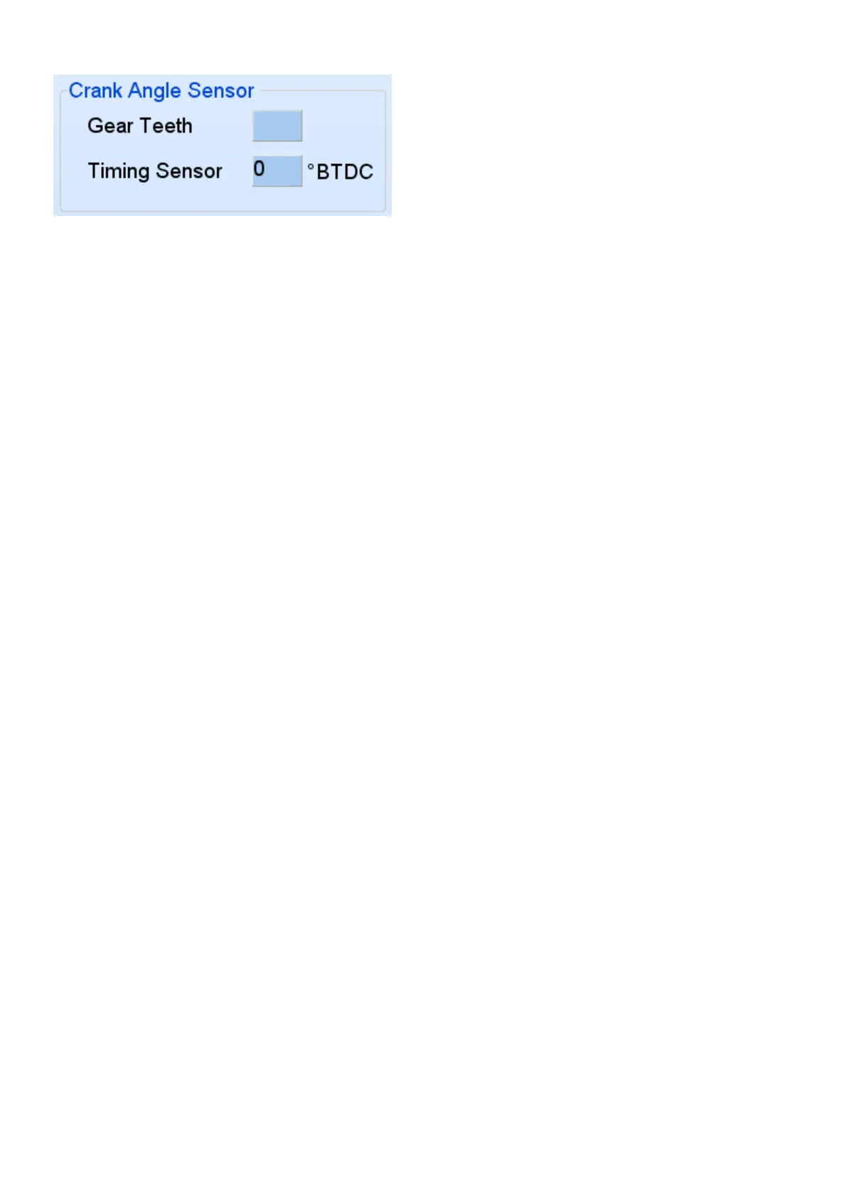
4.12.2 Setting Crank Trigger Timing
This trigger consist of a single sensor and some form of crank gear like 60-2 or 36-1 etc. this setup
requires 2 kinds of settings. One is on which teeth after the slot, TDC is located. The other setting
is a fine tune setting between the teeth to correctly align software timing with engine timing.
If you can see the gear put the engine on TDC. Count the number of teeth from the sensor to the
slot in a clockwise direction. Enter this number of teeth in the software under Gear Teeth. Enter 0
in Timing Sensor °BTDC field. The car should start. Check with the timing light to see if the
software timing correlates with the engine timing. If the difference is less than the tooth pitch
degrees, adjustments can be made on the Timing Sensor °BTDC field. Otherwise add or subtract
one tooth and try again. If you can’t see the gear you can enter speculative values in Gear Teeth.
Disconnect the injector fuses and crank with a timing light. Start with 4 and increase 2 at a time.
When it flashes around 10 degrees save and proceed with starting.
If a magnetic pickup is used, ensure that the positive and negative of the magnetic sensor are
correct. If they are connected wrong way round, the timing will retard instead of advance and the
fazing will be wrong. Sometimes the engine will start but it may not rev up. You can also see this
on the software if the rpm bar jumps erratic between two values not next to each other.
In some cases the teeth count between the slot and the sensor on TDC may be larger than crank
fire pitch. The crank fire pitch can be calculated by the total teeth of the gear, (missing ones