included) multiply by 2 divide by the no of cylinders. This means that a 60-2 gear for a 6 cylinder
engine is 60*2/6=20.
If the teeth between the sensor and slot is ex 25 then you set it at 5 (teeth – pitch) and change the
coil wires in sequence. Coil 1 connects to driver 2, coil 2 connects to driver 3 and coil 3 connects
to driver 1.
If the teeth between the sensor and slot is ex 47 then you set it at 7 (teeth – 2*pitch) and change
the coil wires in sequence. Coil 1 connects to driver 3, coil 2 connects to driver 1 and coil 3
connects to driver 2. For more info in this please see the drawings supplied on CD.
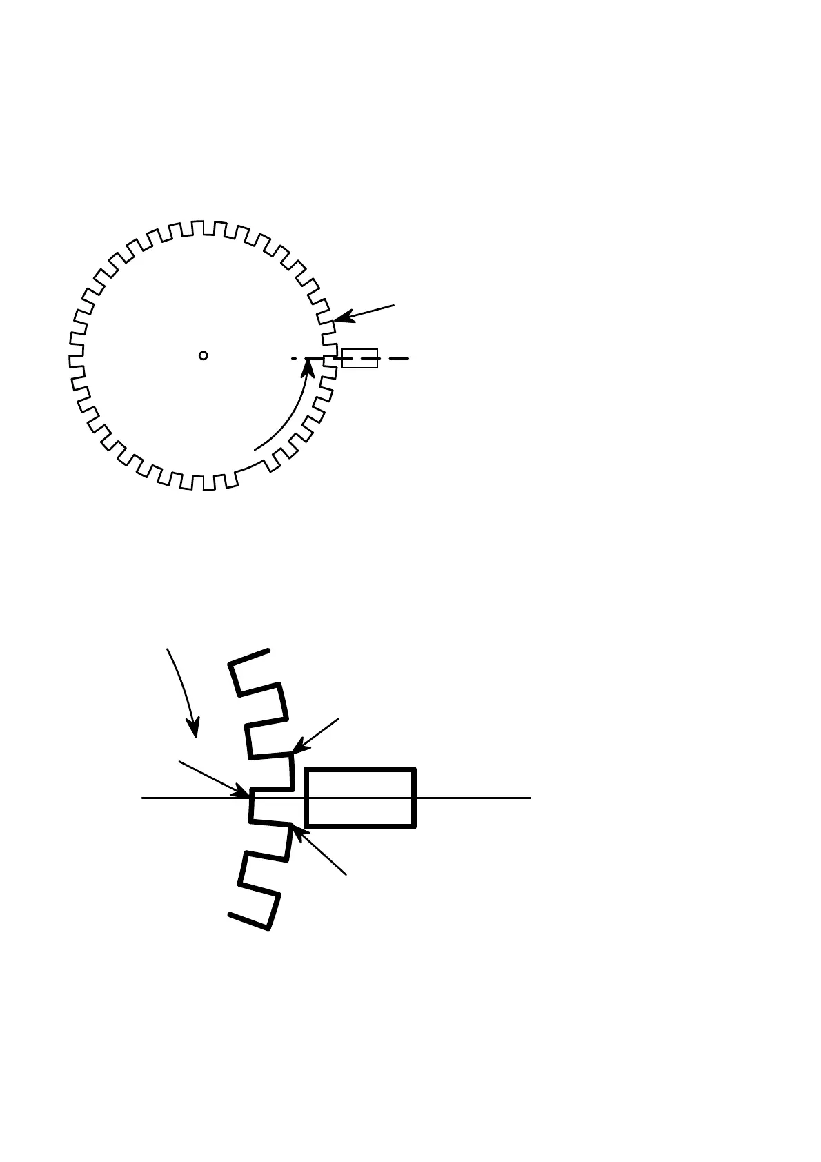
Count anti clockwise from the
slot to the pickup. If the centre of
the pick up sensor is past the last
edge of a tooth, count the next tooth
as well. Put this number in the Gear
teeth block on the Setup page.
last edge of a tooth
centre of the pick up sensor
Example
7 teeth
The trigger point of the sensor is the centre of the sensor to the last edge of the tooth or trigger
plate (Trigger Edge 0°). On a 36-1 gear the pitch is 10 degrees. To ajust the Timing BTDC block
you can guess a setting for the centre of the pickup between the trigger edges of the adjacent
teeth. See the sketch below. When the engine is running, adjust it till the software correlates with
the timing light.
Centre of the pick up sensor
Trigger Edge 0°
Trigger Edge 10° or 0° next tooth
Trigger Edge 6°
Crank Rotation